
US 51628
UNITED STATES PATENT OFFICE.
EBEN T. STARR, OF NEW YORK, N.Y.
IMPROVEMENT IN REVOLVING FIRE-ARMS.
specification forming part of Letters Patent No. 51,628, dated December 19, 1865; antedated December 7, 1865.
To all whom it may concern:
Be it known that I, Eben T. Starr, of the city, county, and State of New York, have invented certain new and useful improvements in Revolving Fire-Arms; and I hereby declare that the following is a full, clear, and exact description of the same, reference being had to the accompanying drawings, forming part of this specification, in which—
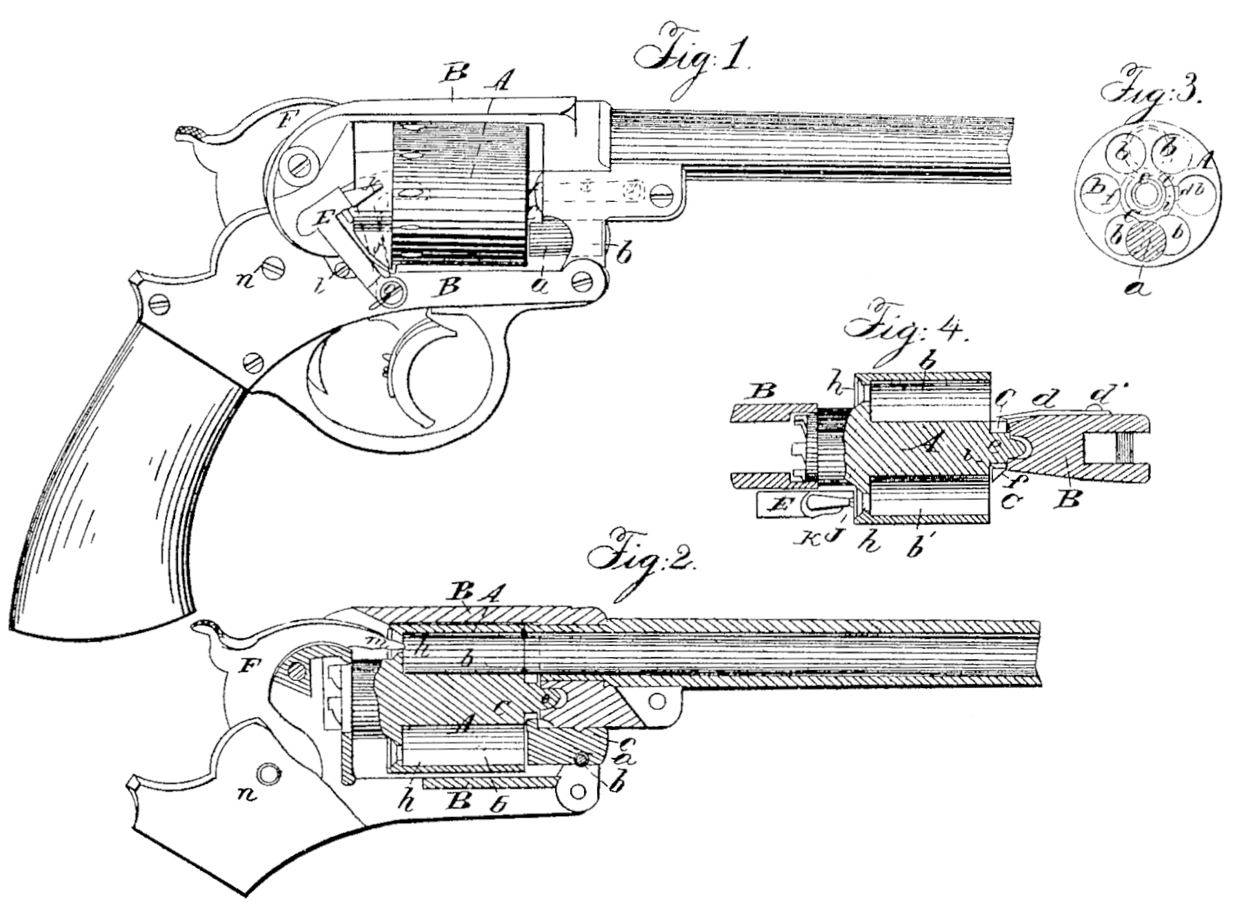
Figure I is a side view of a pistol with my improvements. Fig.2 is a central longitudinal vertical section of the principal parts of the same. Fig. 3 is a front view of the cylinder and the cartridge-guard, the latter being partly in section. Fig. 4 is a horizontal section of the cylinder, cartridge-guard,and part of the frame.
Similar, letters of reference indicate corresponding parts in the several figures.
This invention relates to revolvers which are loaded in front of the cylinder with metallic cartridges which contain a fulminate.
It consists in a novel device for preventing the cartridges and cartridge-shells from accidentally slipping out from or forward in the chambers of the cylinder, but which affords facility for the ejection of the discharged shells, or the cartridges themselves, if desired, from the chambers.
It also consists in a novel ejector for ejecting the discharged cartridge-shells or cartridges from the chambers.
To enable others skilled in the art to make and use my invention, I will proceed to describe its construction and operation.
A is the cylinder, constructed for loading in front—that is to say, having bottoms to its chambers, or, in other words, not having the bores of the chambers extended through its rear. This cylinder is applied to rotate with in the frame B, and may be secured therein in any suitable manner.
C is the novel device which I term the “cartridge-guard,” arranged between the front of the cylinder and the frame B, and close to the cylinder, for preventing the cartridges and discharged cartridge-shells from accidentally slipping out from or forward in the cylinder. This guard consists of a plate or piece of steel or other metal of bifurcated or annular form, substantially as shown in Fig. 3, pivoted to the frame B in front of the cylinder and be low the axis thereof. Its pivot a is represented as being formed in the same piece with or rigidly attached to it, and fitted to a circular hole bored through the front part of the frame, and secured against longitudinal displacement, when the cylinder is removed from the frame by means of a transverse pin, b, inserted through the frame B and through a groove, c, in the said pivot; but the guard may be pivoted to the frame in a similar position in any other manner. The guard is large enough externally to cover portions of the mouths of as many of the several chambers b b’ as are not either wholly or partly covered by the rear end of the barrel, which fits close against the front end of the cylinder. This is illustrated in Fig. 3, in which the rear end of the barrel is shown in red outline covering the mouths of the two upper chambers, and the mouths of the other chambers are all shown as partly covered by the fork or ring, so that the cartridges contained therein cannot slip forward, the shells of the cartridges which are employed being just of the full length of the chambers. The guard is held in the necessary position to do this by means of a spring, d, which is secured by a screw; d’, to the left side of the frame, in front of the cylinder, and which presses the guard into contact with the front journal, e, or axis-pin. The said spring d appears on the right side of the guard in Fig. 3; but it must be borne in mind that this is a front view, and represents the sides reversed. The opening i. provided in the guard to admit the front journal of the cylinder or the axis-pin is wide enough to allow the guard to be pressed aside, as shown in red outline. in Fig. 3, far enough to uncover the mouths of the chambers as they are severally brought by the revolution of the cylinder to the position of that marked b’—viz., directly at the right of the axis of the cylinder, which is the position for loading, and which allows the cartridge to be inserted past the right side of the front portion of the frame.
It will be seen by reference to Fig. 3 that the portion of the guard on the last-mentioned side of its opening i is narrower than that on the opposite to permit its movement to be made in the proper direction from its central position (shown in that figure in black outline,) in which it covers parts of all the chambers not covered or partly covered by the barrel.
To enable the guard to be pushed aside in loading, it is beveled externally from the front on the loading side, as shown at f in Figs. 1, 3, and 4.
The cartridge being placed against the side of the frame, in front of the guard, parallel, or nearly so, with the axis of the cylinder, and opposite to the chamber, in the position of that marked b’, is pushed back by the thumb and finger against the bevel f with sufficient force to overcome the pressure of the spring d, and so push aside the guard far enough to uncover the said chamber and allow the cartridge to enter, and the cartridge may then be pushed back into the chamber. When the cartridge has been pushed home the guard is pressed back by the spring d to the position shown in Figs. 3 and 4. When the discharged shell or cartridge is to be withdrawn from the chamber the guard is pushed aside far enough to uncover the mouth of the chamber by the pressure of the thumb applied to it on the-loading side. The guard C might be so constructed that the portion on the loading side only shall be movable.
E, Fig. 1, is the ejector for ejecting the discharged cartridge-shells or the cartridges from the chambers. This is made in the form of a hammer, and arranged to operate in the arc of a circle on the right-hand or loading side of the frame A, behind the cylinder, where it is pivoted by a screw, g, to the lower part of the frame. To allow this ejector to be used the cylinder has an opening, h, Fig. 2, provided in the rear of each chamber, into which the nose or point K of the ejector can enter and pass to push the cartridge-shell or cartridge far enough forward from the chamber to enable its frontend part to be laid hold of in front of the cylinder by the thumb and finger and thereby drawn out. The opening h is the same through which the hammer F strikes to/explode the fulminate in the cartridge. The/said ejector is so arranged that its point or nose K may enter the chambers as they are severally brought to the position of the chamber. (Marked b’ in Figs 3 and 4.) A spring, j, is so applied in front of this ejector as to press it back and keep it pressed back against a stop-screw, l, or other equivalent projection on the frame A, as shown in Fig. 1 in black outline, out of the way of the cylinder,at all times but when it is desired to expel the cartridges or shells from the chambers. When the chambers are brought to the position of b’, before mentioned, the ejector may be pressed forward by the thumb to the position shown in red outline in Fig. 1., and its nose, entering the opposite chamber, pushes forward the cartridge-shell or cartridge from the said chamber.
F is the hammer, made with a nose, m, of pointed or other suitable form, to enter the openings h provided in the cylinder communicating with the several chambers near the centers or axes of the bores thereof, and having its center of motion n so arranged as to permit the said nose to strike in a forward direction into the said openings, as shown in Fig. 2, when the chambers are severally brought into line with the barrel for firing. By this construction and arrangement of the hammer, in combination with suitable openings, h, in the rear of the chambers of the cylinders, I am en abled to use fixed-ammunition cartridges, made with what is termed a “central fire”— that is to say, having the fulminate arranged in the centers of their bottoms, without the interposition of a pin between the hammer and the cartridges— thus enabling central-fire cartridges to be used in a revolver of a simpler construction than any in which such cartridges have been heretofore used. The cartridges are supported against the forward blow of the hammer by having the shells made of a length equal to the full length of the chambers, so that their front ends will bear against the rear end of the barrel.
What I claim as my invention, and desire to secure by Letters Patent, is—
1. The cartridge-guard C, constructed, applied, and operating under the control of a, spring, d, substantially as herein specified.
2. The ejector E, arranged to operate in the arc of a circle it rear of the cylinder, on one side of the frame of a revolving fire-arm, and operating substantially as herein set forth.
EBEN T. STARR.
Witnesses:
Henry T. Brown,
J. W. Coombs.