
US 51690
UNITED STATES PATENT OFFICE.
GEORGE C. BUNSEN, OF BELLEVILLE, ILLINOIS.
IMPROVEMENT IN REVOLVING FIRE-ARMS.
Specification forming part of Letters Patent No. 51,690, dated December 26, 1865.
To all whom it may concern:
Be it known that I, George C. Bunsen, of Belleville, in the county of St. Clair and State of Illinois, have invented new and useful Improvements in Fire-Arms; and I do hereby declare that the following is a full, clear, and exact description thereof, which will enable others skilled in the art to make and use the same, reference being had to the accompanying drawings, forming part of this specification, in which—
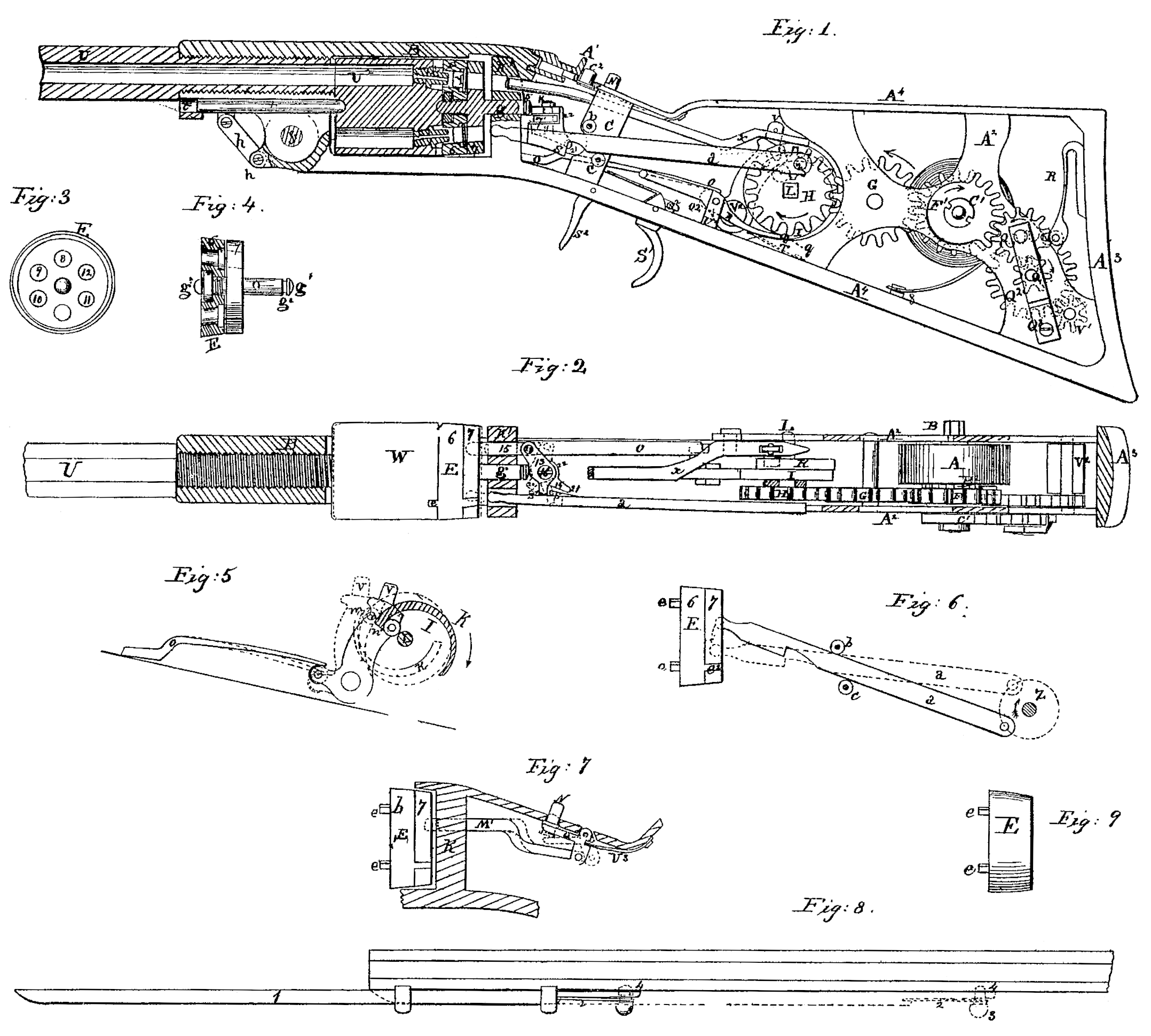
Figure 1 is a plan view, as seen from the left side, of the butt and stock and of the operating parts and part of the barrel of a gun containing my improvements, the cover being removed to show the parts. Fig. 2 is a view, partly in section, on a longitudinal line passing above the spring A, and showing some of the parts in elevation, the casing of both sides of the butt being removed. Fig. 3 is a plan of the disk which lies behind the cylinder of the gun, and Fig. 4 is a vertical section thereof. Fig. 5 is a view of the cocker and of some of its connections. Fig. 6 is a view of the lever which rotates the disk and cylinder. Fig. 7 is a de tailed view of the safety-guard. Fig. 8 is a detail showing the manner of attaching the bayonet.
Similar letters of reference indicate like parts.
My object in this invention is to produce a repeating-rifle which will not need to be revolved by the hand for every shot. An arm of this sort will be of great advantage in deer hunting, as it will allow the hunter to keep sight on the running deer while the gun discharges the contents of its cylinder in a successive series automatically. It will also be of great service in hunting other game and for military uses.
Ordinary revolvers or repeating fire-arms cannot accomplish like results with my arm in hunting swift-running animals, as they take too much time to be got ready for each succeeding discharge, and the hunter has to lose sight in the act of cocking the piece. In shooting water-fowl at a great distance a rifle-barrel for 0 sized shot, arranged after my invention, Would do great execution, as a many-chambered breech for that size of shot might be made to hold ten to fifteen charges without being too bulky, and two shot might be loaded in each chamber and the whole discharged in about two seconds, having greater range than a shot-gun, and being made to scatter by the hunter in moving his aim along the line of the object, whether the same be stationary or running game or a flock of birds in flight. My plan may also be used for smooth-bored guns, giving the hunter six shots through one barrel, (where a cylinder with six chambers is used,) which he might discharge singly or in rapid succession.
Fig. 1 shows the butt of a gun made hollow to receive the operating parts seen in the figure. Stay-pieces A^2 are firmly secured to the facings A^4,in order to sustain the Works within and to furnish bearings for the shafts of the pinions and other devices. A hollow shaft or arbor, B, secured in the stay-pieces in the lower part of the butt carries a spring, A, whose outer end is fastened to the inside of the butt. The arbor is carried upon a solid shaft, to which the pinion F is secured. The shaft and hollow arbor are connected by a spring-pawl and ratchet in the usual manner, so that the hollow arbor turns loosely on the shaft when the spring is wound up and engages with it to drive the pinion when it revolves in the opposite direction. The spring is wound up by applying a key to the projecting end of the hollow arbor. The pinion-wheel F is secured on its shaft on the inside of the side or stay piece, and the shaft projects beyond its bearing on that side, in order to receive another pinion-wheel, C’, which is held thereon by a This pinion-wheel C’ is smooth upon more than one-half of its periphery. Its teeth gear with a gear-wheel, Q, which meshes with a smaller gear, Q’, the journals of both the latter gears being sustained in the stay-piece at one end and in a bracket, Q^3, at the other end, and the shaft of the gear Q’ extending within the stay-piece so as to carry a gear, Q^2, which gears with a wheel, V’, fixed on a shaft extending from one stay-piece to the other, and carrying a fan-wheel, V^2.
The gear-wheel F meshes with the gear G, and that with the gear H, the shaft of the latter being journaled at one end in one of the side or stay pieces and near its other end in a standard, c’, (shown in section in Fig. 2.) which is to be properly secured against the inside of the stay or side pieces, or else to the facings. The gear His fastened upon the end of its shaft L, outside of the standard c’. A lever, a, secured to a crank-pin, z, upon the outside of the gear H, extends between two fulcrum-pins, b c, which are fixed in the sides of two stay-plates, C, (one of which is shown in Fig. 1) which extend from one of the facings A^4 to the other. The lever a is rounded at its end and made to fit the holes 8 9, &c., of the disk E, and has a hook, s, formed on its under side just beyond the pins bc, and a hook or dog, s’, on its inner face, as seen in two different positions of the lever in Fig. 2. The revolution of the crank z will cause the lever a to be alternately advanced and withdrawn, so as to enter and retire from one of the holes 8 9, &c., of the disk, and by reason of the bearing or fulcrum pins b c the levers will have a vertical movement also, which will enable it to rotate the disk during all the time that its end is in one of the holes 8 9, &c., the adjustments of these parts being such as that the rotation of the disk by these means shall be exactly equal to the distance from the center of one of the holes to the center of the next one.
U is the barrel, and K’ the stock, of the gun, secured together by a screw-joint. The stock receives the rotating cylinder W, the rotating disk E, and a stationary partition, K’, secured within the stock, and which is perforated to permit the passage through it of the lever a, the hammer ac, the tampion 15, the finger M’ of the safety-guard, and the axle or shaft g of the disk E, the perforation for the lever a being a vertical slot of length sufficient to allow of the vertical movement of the lever. The stock is divided into longitudinal sections, which are secured to each other below by means of an ordinary joint and screw-pin, f, and above by a sliding catch, A’, which latches over and into a notch cut in the end of the stock, as seen in Fig. 1. The catch is held in the position there seen by a knob, c^2, which is held up before the catch by a spring beneath, (seen in dotted outline in Fig. 1.) When the knob is pressed down the catch can be with drawn and the stock released, so that it may be opened to withdraw the cylinder W. The cylinder is centered in front by the sliding point t, and behind by the projecting end of axle g of the rotating disk. The bolt t slides in a socket, t’, made in the lower part of the stock, and is moved by a link, h, loosely jointed to the bolt and to a hub, h’, below the joint f. When the stock is opened the hub h’, being brought nearer to the under side of the barrel, starts the bolt out of its socket in the cylinder by impelling the link h.
The disk E is made in sections 6 and 7, the latter having an axle, 1, which passes through the section 6, to which it is secured by a nut screwed upon a thread cut upon it, as seen in Fig. 4, the end g^3 of the axle projecting beyond section 6, as shown. The other end of the axle extends far enough beyond the disk to reach through and beyond the partition K’, its extreme end g being rounded, and a groove, g^2, being cut upon it near its end, which receives the fork of a flat spring, 5, secured to the partition K, whereby the disk is drawn backward away from the cylinder. The perforations of the disk must coincide in number and position with the cones U, which communicate with the chambers U^2 of the cylinder. Section 6 of the disk is shown divided in Fig. 4, so as to show the shape of its perforations. These are made hat-shape, so as to receive solid blocks of corresponding shape, resembling coopers’ rivets, whose flanges are, by the junction of the two parts of the disk, secured in the enlarged portions of the perforations, within which they are free to move end wise by the difference between the thickness of their flanges and the depth of the sockets which receive them. When the cylinder is capped and in place the space seen in Fig. 1 between the cones and the ends of the blocks is taken up by the caps, so that the caps and blocks will be in contact.
A standard, 17, extending from the face of the partition K”, supports a block (designated by the Figs. 13 and 14) by means of a fulcrum pins, 16. In this illustration of my invention I have shown the block composed of two parts, which are secured by the pin 16 on opposite sides of their standard. A sliding bolt or tampion, 15, is loosely hinged to the parts 13 and 14 of the block. The part 13 has an arm, 20, which, in the advance of the lever a, is struck by its dog S’, whereby the block, being rotated on the pin 16, is made to withdraw the tampion out of whatever hole of the disk it occupied. The other part, 14, of the block has an arm, 21, which stretches across the path of hooks of the lever a, which, on its backward movement, draws the block 14 around so as to cause the tampion to enter another hole of the disk. The part 14 of the block extends, as at 22, behind the part 13, so as to form an ear, through which the joint-pin 23, that connects the tampion to both parts of the block, can pass. The part 13 of the block is so curved on the side which is opposite to the end g’ of the axle of the disk as to form a calm, which, when the tampion is forced into a hole of the disk, presses against the end g’, and thus forces the disk snugly against the cylinder, to close the joints between them and between the cylinder and barrel and prevent the leaking of the gases from the cylinder, and when it is withdrawn therefrom presents its lesser face opposite the axle, thereby permitting the spring 5 to withdraw the disk away from the cylinder, in order that the disk and cylinder may be freely rotated. The sections 6 and 7 of the disk are fitted together by ears e^2, projecting from the section 6 and fitting in recesses cut on the periphery of section 7, whereby they are made to rotate together. Like ears, e, projecting from the other side of section 6, fit into recesses cut in the periphery of the cylinder.
X is the hammer-rod, whose free end is sustained in the partition K’, through which it passes in a hole coinciding successively with the holes in the disk E, and its inner end is secured by a loose joint to the hammer V, which is pivoted at V^2 to the frame of the butt, and is constantly drawn forward by the tension of a flat spring, O, which bears on a friction-roller, O^2, secured in a shoulder near its fulcrum V^2, and operates the hammer, and thereby explodes the cap. A friction-roller, in, is secured to the side of the hammer near its top, which is caught at each revolution of the pinion H by a cocker, K, which is a section of a circle or ring set eccentrically upon that face of a disk, I, fast on the shaft L, which is adjacent to the hammer. The cocker K (shown in two positions in Fig. 5) is pointed at that end which is farthest from its center of motion Li, so that it can readily, when its disk is revolved, seize the friction-roller n’, and thereby draw the hammer and its rod backward. When the cocker has moved to the position shown in blue in Fig. 5 it has drawn the hammer back to its farthest limit in that direction, ready to be released so soon as its continual revolution carries its base n’ past the roller n. In this position it is held by means of the tumbler R, which at this moment catches against a shoulder or notch cut on the periphery of the disk I, and prevents the further rotation of the disk and the cocker. This end of the tumbler R is held continually toward the periphery of the disk by a spring, T, (seen in Fig. 1.) The tumbler (see Fig. 1) extends be yond its fulcrum U, so that its other end lies directly over the levers of the hair-trigger S’ and the common trigger S^2, which will, when constructed and operated in the ordinary way, strike the tumbler and disengage it from the disk I, and thereby release the hammer.
It is evident from the above description that when this is done the disk will continue to revolve by means of the tension of the spring A, driving the train of pinions which connect its shaft with the shaft II until its tension is exhausted, thereby operating the hammer and its rod once at each revolution of the cocker, unless the trigger is released by the finger, in which case the spring T will force the tumbler again up toward the disk, so as to catch against its shoulder, after the manner of a detent and ratchet.
In order to prevent a discharge by the premature action of the hammer by the accidental unlocking of the tumbler, the cylinder can be removed from the gun and carried about the person; and whether this is or is not done I have attempted to guard against and prevent the accidental or premature discharge of the piece by means of a safety-guard, consisting of a locking-bolt, M’, whose free end passes into one of the holes of the disk E, its other end being loosely jointed to the shorter arm of a right-angled lever, Q, which is attached to the frame of the butt just behind the locking-slide A’, so as to swing freely on a fulcrum. A spring, U^3, forces the longer arm of this lever up against the frame of the butt, thereby forcing the bolt M into one of the holes of the disk, so as to prevent its rotation, whether the cocker be free to revolve or not.
A thumb-bolt, N, having a flange at its base, is inserted within a hole cut through the frame of the stock just opposite the end of the longer arm of the lever Q, so as to project upon the outside. Whenever sufficient pressure is made on this bolt the sliding bolt will be withdrawn from the disk, and it and the cylinder, will be free to rotate.
The fan-wheel V^@ is driven by the train of gearing V’ Q^2 Q’ Q and the fractional or segment gear C’, and which are so arranged as to produce the greatest possible speed for the fan-wheel. The fan revolves only while the segment-gear is engaged with the gear Q. The object of the fan-wheel is to retard the revolution of the cocker, so as to give the hammer sufficient time to strike before it is again caught by the cocker; and as the whole force of the spring is needed at the time when the disk and cylinder are being rotated, I stop the fan altogether during that part of the movement by using a segment-gear, C’, to drive the fan. The meshing of the gears Q and C’ are insured at each new engagement or revolution of the segment by means of the spring-brake R, which presses continually against the teeth of the gear Q, so that when in a state of rest its teeth shall be in position to mesh with the segment when its teeth are again brought round.
The bayonet 1 (shown in Fig. 8) slides in sockets made beneath the barrel, and is secured or locked in two different positions, either advanced for use or withdrawn, as shown in red outline, by means of a bolt passing through the Inner end of the bayonet, and secured by a spring, which presses it constantly against the barrel, so as to lock the bolt in one or the other of two holes, 4, drilled in the barrel. It is only necessary to withdraw the bolt in or der to slide the bayonet to one or the other of its two positions.
Fig. 9 shows the disk E made in one solid piece instead of two, as in the other figures. When thus made the leakage of the gases from the explosion of the caps and charge among the operating parts behind may be pre vented by securing the blocks Y by means of a washer or equivalent device, which will secure them in place and permit the action of the lever at and the hammer and rod and the bolts that enter the disk, and at the same time shut out the gases from entering the hollow butt of the gun.
When the gun is to be fired in single shots the safety-guard bolt M’ is to be left in place, locking the disk E, when a pull on the trigger will bring the hammer down on the cap. The cylinder is to be then partially rotated for another shot by pressing the thumb on the bolt N, in order to unlock the disk at the same time that the trigger is pulled, when the unlocking of the disk I from the tumbler will cause the lever a to rotate the disk E, and the cylinder is ready for another discharge. If the thumb-bolt N is kept pressed down by the thumb and the trigger is held back against the tumbler, the spring A will cause the hammer to repeat its action and the cylinder to be rotated with out cessation until all the chambers are discharged or the force of the spring is exhausted; but if the cylinder is to be rotated only for another discharge, the thumb-bolt and hair-trigger are to be operated at the same time and at once released, which will cause the cylinder to expose the next cap to the hammer, and an other chamber will be discharged, when it will be immediately locked again by the bolt M’.
The spring-detent R carries a friction-roller, R, on the bearing end or surface which comes in contact with the pinion Q, so that while the force of its spring will break or retard the speed of the gearing the detent will also suffer the teeth of the pinion to pass under it without any possibility of actually locking it; and, further more, when the pinion Q ceases to move by reason that the teeth of the segment-gear C’ have passed out of contact with it, the friction roller R will so act as that the detent will not rest on the point of a tooth, but will roll so as to bring it between two adjacent teeth, and thereby secure the meshing of the segment and the pinion Q, and the adjustment of the detent and pinions are to be made with that object in view.
It is necessary, in order to the perfect action of my gun, that the rotation of the cylinder and the cocking of the hammer be effected with the utmost rapidity, and that the blow of the hammer should be given when the cylinder is at rest. I have therefore so organized the mechanism above described as to retard its action during that period by means of the fractional or segment gear C’ and its train of gearing Q Q’ Q^2 Q^3, which will take up so much of the -power of the spring A as is required to drive them, and in so much decrease the speed of the mechanism, thereby giving the hammer time to give its blow before it is again caught by the cocker. The fan-wheel is added to assist the train of gearing in producing this effect.
I claim as new and desire to secure by Letters Patent—
1. A revolving fire-arm adapted, in the manner herein described, to discharge the chambers of the cylinder successively through one barrel by a single pull of the trigger.
2. The cocker K for operating the hammer, constructed and operated substantially as above described.
3. The lever a for rotating the cylinder, in combination with the crank that drives it and the fulcrum-pins bc, or their equivalents, substantially as described.
4. The disk E, made in two sections, with solid blocks Y in their perforations to receive the blows of the hammer and prevent the escape of gas into the hollow butt, substantially as described.
5. The combination, with the lever a, of the lever-block 13 14, operating upon the bolt 15, as described, to lock and unlock the revolving cylinder.
6. In combination with the parts specified in the preceding clause, the eccentric surface On the block 13 to close the disk against the cylinder, and the spring 5 to withdraw said disk.
7. The combination of the fan-wheel with the Segment-wheel c and the mechanism for rotating the disk I and operating the cocker and the lever a, substantially as described.
8. The segment or fractional pinion C’ and its train of gearing Q Q’, &c., so arranged with the mechanism which cocks the hammer and rotates the cylinder as to be in action to retard the speed of the mechanism when the hammer is striking the cap, substantially as described.
GEORGE C. BUNSEN.
Witnesses:
Theo. Tusch,
M. M. Livingston.