
USA 14118
UNITED STATES PATENT OFFICE.
EBEN T. STARR, OF NEW YORK, N.Y.
IMPROVEMENT IN REVOLVING FIRE-ARMS.
Specification forming part of Letters Patent No. 14, as, dated January 15, 1856.
To all whom it may concern:
Beit known that I, E. T. Starr, of the city, county, and State of New York, have invented certain new and useful Improvements in Fire-Arms, of which the following is a full, clear, aid exact description, reference being had to the accompanying drawings, making part of this specification, in which—
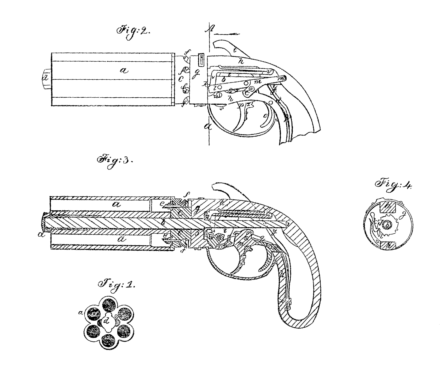
Figure 1 is an end or muzzle view; Fig. 2, a view of the side with the stock removed; Fig. 3, a longitudinal section, and Fig. 4, a cross section taken at line A a of Fig. 2.
The same letters indicate like parts in all the figures.
The first part of my said invention relates to that class of fire-arms in which a series of barrels are arranged or formed about and turn on a common center that the several charges may be brought in succession around to the hammer of the lock to be discharged; and my said invention consists in mounting the central bore of such a series of barrels on a central rotating arbor which carries the breech-plate for all the chambers or barrels, so that the series of barrels can slide thereon to be pushed forward from the breech-plate to receive the charges into the open rear end thereof and then pushed back and locked against the breech-plate to inclose the charges, the said central arbor being so mounted in the stock, breech-piece, or lock-frame, and so connected with the lock as to be turned by drawing back the finger-lever for the purpose of bringing the barrels successively in line to be discharged; and my said invention also consists in elevating the cock by a finger-lever so combined with a trigger that the cock can be elevated and there held by a catch to be liberated for the discharge, either by touching the trigger with the finger or by continuing to pull the said finger-lever after elevating the cock and making it act upon the trigger.
In the accompanying drawings, a represents a series of barrels made out of one block of metal, the several bores or barrels being arranged in a circle at equal distances around a central bore, which is fitted to a central spindle or arbor, b, on which the series of barrels can slide longitudinally, and to which they are feathered or otherwise so connected as to turn there with that tile several barrels may be brought in succession to be fired. Toward the rear end the said spindle or arbor is formed or provided with a breech-plate, c, the front face of which closes all the barrels a when forced and held against it. On the front end of the spindle there is a turning-key, d, which, when turned in the position represented in the drawings, holds the barrels firmly against the breech-plate to confine the charges; but the central bore for a short distance from the muzzle is cut out of a form corresponding with the form of the turning-key d, so that when the key is turned to the proper position the barrels can be pushed forward from the breech-plate to a sufficient distance to admit of inserting the charges into the rear end of the barrels and then pushed back and locked.
From the front face of the breech-plate project a series of pointed punches, e, so located that one will correspond with the center of the bore of each barrel; and by reason of this arrangement, after the cartridges have been inserted and the series of barrels are pushed back, the cartridges are punched to expose the powder to the touch-holes, which pass through the centers of these punches to the nipples f on the rear part of the breech-plate.
The rear face of the breech-plate c fits against the forward face of the metallic breech-piece or shield-plate g of the lock-frame or stock-plate h. The spindle, back of the breech-plate, is fitted to turn, in the manner of a journal, in a central hole in the shield-plate and thence extends back, and its rear end is fitted to turn in the rear stock-plate, as at i, and in this way the spindle is held firmly and can turn freely. Just back of the shield-plate a ratchet-wheel, j, is secured to the spindle b, the number of teeth in the said ratchet wheel being equal to and corresponding in position with the series of barrels. There is a spring catch, k, which takes into the teeth of the ratchet to hold and keep the spindle from turning at the end of each operation; and this catch is disengaged and the spindle rotated at each operation to bring another, barrel in line by the forward end of a spring-hand, l, attached to a lever, m, which at its rear end turns on a fulcrum-pin, m’, in the stock-plate or lock frame. This lever has an inclined slot or mortise, n, which embraces a wrist-pin, o, on the side of the inner end of a finger-lever, p, so that by pulling back the finger-lever the wrist travels in the said mortise and elevates the forward end of the lever m, which brings the front face of the spring-hand l behind the spring-catch k to lift it out of and to liberate it from the ratchet, while at the same time the said hand acts on one of the teeth of the ratchet and turns it to the required distance equal to one tooth to turn the barrels and bring a new charge in line.
The end of the spring-hand l is so formed that in rising it first disengages the spring-catch, then turns the ratchet and permits the spring-catch to fall back to relock the ratchet-wheel when turned to the required extent, and having completed these operations, in returning to its original position it springs outward to pass the spring-catch without disengaging it. The finger-lever is forced back to its forward position at the end of the motions above described by a spring, q, which acts on the inner end thereof.
The forward upper part of the finger-lever is formed with a lip, as at r, which acts on a corresponding but inverted lip on a spring-dog, s, fitted and jointed in a socket in the body of the cock t, which turns on the fulcrum-pin u, so that when the finger-lever is drawn back the lip r on its forward end acts on the corresponding lip on the dog and forces it downward, which turns the cock on its fulcrum-pin, thereby elevating the hammer and contracting the mainspring v, which bears on the forward part of the body of the cock at it, on the opposite side of the fulcrum-pin, and so soon as the hammer is elevated the rear end, thereof at x is caught and held by a spring-catch, y, which holds it. The finger-lever is prevented from moving back any farther by a stop, z, which comes in contact with the lower stock-strap, and so soon as the finger-lever is liberated by the finger it is thrown back to its original position by the tension of the spring q, and then the lock is in condition for the discharge by a trigger, c’, the sear d’ of which acts on the spring-catchy, which liberates the cock or hammer for the discharge. This trigger can be operated to liberate the cock either by the finger acting directly on it after the cock has been elevated by the finger-lever, as above described, or by the continued pull of the said finger-lever, For this purpose the stop z is so connected with the finger-lever that it can slide thereon, and when drawn down to the position represented by dotted lines in Fig. 3 it does not arrest the back movement of the finger-lever, which, after-cocking the hammer, strikes against the trigger and effects the discharge by the one continued pull on the finger-lever. But to do this the finger-lever, after elevating the cock or hammer, must permit the dog to pass, by it as the cock or hammer descends, and for this purpose the continued pull on the finger-lever causes the lip r to pass by the corresponding lip on the spring-dog s, so that the cock will be no longer held by the contact of the lips, and then the continued pull brings the finger-lever against the trigger, which liberates the catch y, that the mainspring may force down the cock or hammer, as if the trigger were operated directly by the finger. In this way the arm can be so set by simply shifting the sliding stop as either to cock and effect the discharge by one single pull of the finger-lever, or simply cocked to be discharged at pleasure by the binger in the usual way, and in either case the finger will be relieved from the tension of the mainspring before the discharge, that aim may be taken for the discharge.
It will be obvious that either of my sail improvements may be used without tie other, although the best results will be obtained when both are used in connection. After the discharge the finger-lever is liberated, and it is then carried back by the spring q, the spring-dogs yielding to permit, the lip r on the finger-lever to pass by and get above the lip on the dog s.
I do not claim as of my invention the cartridge-cutters on the breech-plate, nor any of the separate parts of which my improved arm is composed.
What I claim as my invention, and desire to secure by Letters Patent, is—
1. Mounting the series of barrels on a central rotating spindle or arbor provided with a breech-plate, so that it can slide thereon, substantially as described, to be moved forward to receive the charges and then pushed back and locked to inclose the charges, as set forth.
2. The method of elevating the cock by the finger-lever until it is engaged and held by a spring. catch, substantially as described, in combination with the trigger, so arranged that it can be operated by the continued pull of the finger-lever to effect the discharge, substantially as described.
3. In combination with the finger-lever and trigger, arranged and combined substantially as specified, the employment of the shifting stop on the finger-lever, so that it can be set either to effect the discharge by the continued back pull on the finger-lever or by touching the trigger with the finger after the cock has been elevated, as described.
EBEN T. STARR.
Witnesses:
Wm. H. Bishop,
Andrew De Lacy.