
USA 13581
UNITED STATES PATENT OFFICE.
WILLIAM W. MARSTON, OF NEW YORK, N.Y.
IMPROVEMENT IN FIRE-ARMS.
Specification forming part of Letters Patent No. 13,581, dated September 18, 1855.
To all whom it may concern:
Be it known that I, William W. Marston, of the city, county, and State of New York, have invented, made, and applied to use certain new and useful Improvements in Revolving Fire-Arms; and I do hereby declare that the following is a full, clear, and exact description of the construction and operation of the same, reference being had to the annexed drawings, making part of this specification, wherein—
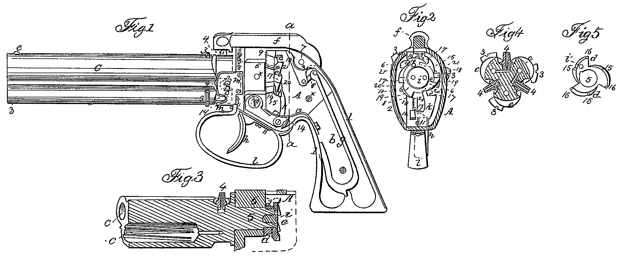
Figure 1 is a side elevation of a pistol fitted with my improvements, as with the cap-plate and side of the handle removed. Fig. 2 is a cross-section at the line a, and Fig. 3 is a longitudinal section through the spindle carrying the revolving barrels. The other figures are separately referred to, and the like marks of reference indicate the same parts.
The nature of my said invention consists in mounting two, three, or more barrels or chambers on a center spindle, which extends back into the stock of the piece, and is provided with cams, through which the trigger is made to rotate said barrels, the act of doing which raises the hammer, so that the first pull of the trigger rotates the barrels about half the amount required and raises the hammer to half-cock, the second pull completes the motion within the smallest possible amount, raising the hammer to full-cock, and the third pull, which is similar to a hair-trigger, turns the barrels the small amount to pass the cam from beneath the tumbler-piece of the hammer and discharge the arm.
In the drawings a pistol is represented; but it will be evident that the same invention might be applied to revolving chambers or breeches or barrels, and that the number of said barrels or chambers may be varied.
b is the stock or handle, formed in any usual manner.
1 1 are the metallic straps from the stock to the the metallic chamber A, carrying the working parts. 2 is the movable cover-plate of this chamber, attached by screws at x x.
e are the barrels, fitted with sights 3 and cones or nipples 4, communicating to the respective barrels by cross-holes plugged at their outer ends. (See Fig. 4, which is a cross-section through said cones.)
5 is a spindle centrally at the rear end of the barrels, either formed with or screwed into the rear end of the barrels, which enters into and through the block 6 in the chamber A, so that the said barrels and spindle can be freely rotated. On the inner end of the spindle a discharging-cam, d, is placed, formed with as many points as there are barrels in the piece, and keyed on; and next behind said cam d is a face-plate, e, formed with the necessary projections used in rotating and stopping the barrel; and the screw i in the rear end of the spindle secures the face-plate and cam into place,and a screw or pin, i, prevents the cam or faceplate from turning the one separately from the other.
f is the hammer, of any usual character, set on a center-pin, 7, and fitted with the bridle 8 to the mainspring g. 9 is the elevating-tumbler on the under side of the hammer, which is so placed as to be acted on by means of the can d in the manner hereinafter set forth.
l, is the trigger on a center-screw, 10, and fitted with a sear, k, that is jointed to the rear end of the arm of said trigger, and provided with a spring, 11, passing up from beneath said arm, so as to force the sear toward the face-plate e, 12 is a spring to throw the trigger forward.
l is the trigger-guard, as usual, and m is a shield passing partly around the rear end of the barrel to protect the caps, and 14 is a notch therein, through which said caps can be supplied or removed.
The operation of the piece is as follows: When it is desired to use the same the trigger h is to be pulled on, which throws up the sear k, the end whereof takes the notch behind the projection 17, rotating the barrels until the stop 13 on the trigger comes against the stop 20 on the edge of the face-plate e, the act of doing which elevates the hammer, the tumbler 9 of which takes the half-cock notch 15. The trigger is then released to be thrown forward by the spring 12, which causes the sear k to take the second projection, 18, and on pulling again on the trigger the barrels are moved nearly to the point to bring the succeeding barrel into the same place as that occupied at the previous discharge of the piece. The stop 13 now takes against the lowest notch of the double stops 21 and the hammer is raised to the full-cock notch 16. If, now, the trigger be released, the sear k cannot descend far enough to take the next projection, 17, so that on pulling the said trigger the sear slides over the back of said projection until it comes against the notch 19, thereby turning the barrels just enough to allow the tumbler 9 to slip off the end of the cam at 16 and strike the cap on the cone 4 and discharge the piece. In this case the stop 13 comes in contact with the stop 21 on the edge of the face-wheel, stopping the father rotation of the barrels, and the parts are again ready to be operated on, as before described, to discharge the next barrel or chamber.
It will be evident that, if so desired, the hammer might be brought up to the full-cock by one pull of the trigger; but I do not prefer the same.
On reference to Fig. 2 it will be seen that the sights on the barrel which is in the position to be exploded are on a line clear of the side of the chamber A, so that the trigger is to be pulled twice and then the piece aimed by means of the sights, and then the slight pull of the trigger discharges the arm without perceptible alteration in the aim or direction of the barrel.
The hammer may be so formed that it can be held up by hand while the caps are being placed on the cones; or the barrels may be fitted with any convenient stop to prevent their accidental rotation and the consequent firing of the piece; or any suitable stop may be fitted to prevent the hammer descending on the caps, except when the stop is removed, and for this purpose a screw through the hammer itself, with a head that can be turned by hand, may be made use of to raise the hammer slightly from the nipples or cones and the caps on them.
I do not limit myself to the size or character of arm fitted with my improvements; neither do I make any claim for rotating and cocking a fire-arm simultaneously; neither do I claim the sear k to act upward and rotate the barrels, as this is also well known; but
What I claim, and desire to secure by Letters Patent, is—
1. Elevating the hammer to cock and discharge the piece by means of a cam, d, revolving with the barrels or chambers and formed with as many points as there are barrels or chambers, so that the hammer shall be raised and discharged by simply rotating said barrels or chambers, as specified.
2. The revolving face-plate e, formed with projections on its face to take the sear k, and with notches on its edge taking the stop 13 on the trigger, the two acting to rotate and stop the barrels at the precise point required and prevent the strain on the trigger from turning the barrels too far, as specified.
3. The mode herein specified of constructing and fitting the parts of the cam d, face-plate e, trigger h, sear k, and stop 13, so that the hammer shall be cocked by one, two, or more pulls on the trigger, and then discharged by another slight pull of the trigger, in the manner and as specified.
In witness whereof I have hereunto set my signature this 6th day of August, 1855.
W. W. MARSTON.
Witnesses:
Lemuel W. Serrel,
Thomas G. Harold.