
USA 13582
UNITED STATES PATENT OFFICE.
F. NEWBURY, OF ALBANY, NEW YORK.
IMPROVEMENT IN REVOLVING FREARMS.
Specification forming part of Letters Patent No. 13,582, dated September 18, 1855.
To all whom it may concern:
Be it known that I, Frederick Newbury, of the city of Albany, State of New York, have invented certain Improvements in the Construction of Fire-Arms, of which I declare the following specification, with the drawings hereto annexed as part of the same, to be a full and perfect description.
Similar letters in the drawings denote the same parts of the apparatus.
My invention relates to the construction of revolving-cylinder many-chambered fire-arms.
My first improvement is in the construction of the lock— that is, in the machinery by which the cylinder is turned round and the charge of each chamber fired in succession by the pulling of the trigger.
My second improvement is in the mode of attaching and detaching the barrel from the face of the cylinder when necessary.
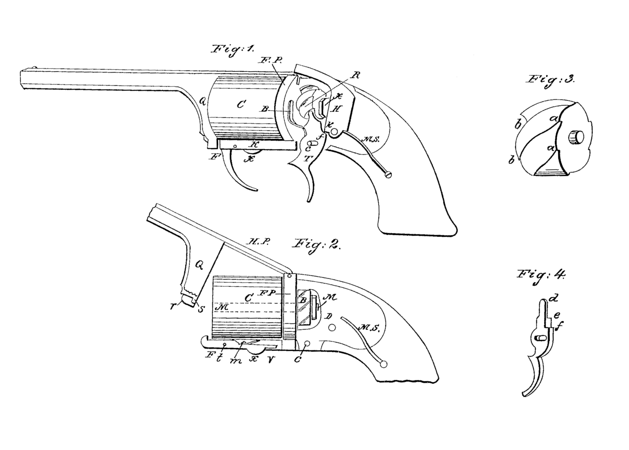
Figure 1 represents a pistol with a portion of the stock and lock-plate removed to show the internal construction of the working parts of the lock. Fig. 2 represents a fragment of the pistol, showing the method of attaching and detaching the cylinder and of removing the barrel for that purpose. Figs, 3 and 4 are separate parts of the apparatus.
The cylinder A is kept in place by being fixed upon a shaft or mandrel, M, shown by dotted lines in Fig. 2, which, passing through its center, continues by an orifice or bearing through the face-plate F P, in which it (the mandrel) revolves, to another bearing in a standard, D, secured to the stock a short distance behind the face-plate. The cylinder and mandrel must revolve together, and for that purpose either that portion of the mandrel that fits within the cylinder is of a square or polygonal form or a portion of it within the back part of the cylinder is made in that manner.
Upon the mandrel, between the face-plate and the standard D, is secured a ratchet-wheel, R. The teeth of this wheel do not range, as usual, in the plane of its axis, but obliquely, so that the upper angle, a, of one tooth shall be a trifle higher than the lower angle, b, of the other, (see Fig. 3, which is a perspective view of the ratchet-wheel,) and the number of teeth of the wheel must equal that of the number of chambers in the cylinder. In the drawings the wheel is for a six-chambered revolver.
The trigger T turns on a pin, c, which enters a slot, as shown in the drawings, which slot allows the trigger a sliding as well as rotating motion. The upper end of the trigger is formed (see Fig. 4, which is a perspective plan of it) into a projecting upper limb, d, leaving a shoulder at e. When the trigger, is drawn the limb d enters into the angular recess be hind one of the ratchet-teeth, at a, and as it is pressed forward compels the wheel R to turn round until it has moved round one-sixth of its circuit. The trigger has just above its axis, on its back part, a square projection, f, which locks into a corresponding projection, k, in the hammer H. Consequently when the trigger is drawn and the cylinder is revolving the hammer gradually rises until the instant that the cylinder, reaching the last point of its movement, has placed a chamber in line with the barrel, when the points f and h pass each other, releasing the hammer, which is instantly thrown forward by the mainspring M S upon the priming-cap.
The shoulder e of the trigger is so adjusted that just at the moment of the discharge it presses against the edge of the ratchet-wheel, so as to hold the barrel immovable during the discharge. As soon as the trigger is released from the pressure of the finger the spring B throws it back, the play of the pin C in the slot allowing the points k and f to repass each other and resume their first positions.
The method of attaching and detaching the barrel to and from the face of the cylinder consists in attaching it to the face-plate F P by extending the upper part of the barrel as a flattened bar or hinged plate HP, pivoting the same to the upper edge of the face-plate by a forked extension, the fork embracing the recess in which the hammer lies when down. From the rear end of the barrel a block of metal, Q, extends downward, so as when in position to rest against the cylinder and to reach the lowest part of the stock at F. In the bottom part of this block is a recess, r, with stop S. Within the bar K, which forms that part of the stock underneath the cylinder, is a recess containing a catch-lever, m, pivoted at t, with its outward end formed into a strong hook-catch to hold onto the stop S when the barrel is brought down to its place. The lever-catch is kept against the stop by the spring v, Fig. 2, and is released by the finger-piece X, which is the only part of the apparatus projecting beyond the stock. This arrangement of the catch and the position of the finger-piece under the guard secures it from disturbance and renders it almost impossible to loosen the barrel and cylinder without design.
I do not claim the use of an oblique toothed ratchet-wheel, nor the revolving mandrel attached to both cylinder and ratchet-wheel; but
I do claim—
1. The method of operating an oblique toothed ratchet-wheel by the direct action of the upper limb or cam end of the trigger, which trigger also by the same action cocks and discharges the hammer and holds the cylinder firmly in place during the firing of the piece, substantially as set forth in the above specification.
2. The employment and use of a slot in the trigger for the traverse of its center-pin or axis, in combination with the action of the trigger directly upon the hammer in order to enable the trigger to replace itself behind the hammer as before the discharge of the same, substantially as set forth in the above specification.
3. The apparatus for attaching and detaching the barrel to the stock— to wit, the catch lever lying in the stock underneath the cylinder, with its hook and finger-piece and spring, together with the recess and stop in the block Q.
F. NEWBURY.
Witnesses:
Richd. Varick De Witt,
W. C. Miller.