
US 255573
UNITED STATES PATENT OFFICE.
EDOUARD BLED, OF PARIS, FRANCE.
LOCK FOR FIRE-ARMS
SPECIFICATION forming part of Letters Patent No. 255,573, dated March 28, 1882.
Application filed January 20, 1882. (No model.) Patented in Belgium March 15, 1880, and December 15, 1880.
To all whom it may concern:
Be it known that I, EDOUARD BLED, of Paris, in the Republic of France, have invented certain new and useful Improvements in the Lock Mechanism of Fire-Arms, of which the following is a full, clear, and exact description.
Reference is to be had to the accompanying drawings, forming part of this specification, in which similar letters of reference indicate corresponding parts in all the figures.
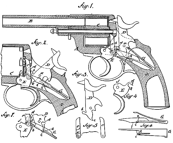
Figure 1 represents a vertical longitudinal section of a fire-arm having a revolving cartridge cylinder or chamber, and showing the hammer at half-cock. Fig. 2 is a similar view of the same, in part, with the hammer at full cock. Figs. 3, 4, 5, and 6 are views of details detached, Fig. 3 being a side view of the hammer, Fig. 4 a side view of the trigger, Fig. 5 a side view and longitudinal section of the pawl which operates the cartridge-cylinder, and Fig. 6 a side view and plan of the main spring. Fig. 7 is a side view of the several details, in part, in their relation with each other when the spring is in the act of bringing the hammer to half-cock.
This invention, although applicable to fire-arms generally, is more particularly designed to be applied to revolvers, and will here be described accordingly.
The invention consists in certain combinations, with the hammer, of the trigger of the fire-arm, whereby intermediate parts for controlling the hammer by the trigger are dispensed with, and the trigger acts directly in a very simple and perfect manner upon the hammer to raise or draw it back.
The invention also consists in a peculiar construction and arrangement of the mainspring, including a secondary spring formed in or out of the mainspring, and operating to bring the trigger under the hammer after the hammer has been brought to half-cock.
A is the stock of a revolver, B its barrel, and C therevolving cartridge cylinder or cham 45 ber.
D is the hammer, and a its pivot. Said hammer is formed or provided with a lower front projecting catch, b, and with a back lower projection, c.
E is the trigger, provided with an upper back projection, d, having a notch in its end, and arranged so as to be raised by the projecting catch b of the hammer when the hammer is acted upon directly by the thumb to work it back.
Pivoted to the trigger is the pawl e, by which the cartridge-cylinder C is intermittently rotated to bring its cartridge-chambers successively in line with the barrel. Said cylinder is held in position by a projection, f, on the trigger engaging with any one of a series of notches in the cylinder, as shown in Fig. 2.
G is the mainspring, which is a double one having upper and lower main arms or branches. The upper branch acts directly upon or under the hammer, while the lower branch is extended, so as to act directly upon a cam, g, formed in or on the pawl e, or when the fire-arm is not a revolver, then the lower branch of the mainspring acts directly on the trigger. As here shown, however, the mainspring serves to keep the said pawl in engaging contact with the cartridge-cylinder, and the trigger is also controlled by the downward pressure of the spring. The lower branch of the mainspring is of a flattened construction back of its extension, which operates upon the pawl and trigger. This flattened portion h of the spring is beveled off at its forward end, as shown in Fig. 6, and has a longitudinal cut made in it to form in or out of the mainspring a secondary spring, i, which has a rounded forward extremity. The object of this special construction of the main spring will be hereinafter explained.
The action of the lock mechanism is as follows: When the trigger E is pulled back by tle finger a lower projection, k, on its rear portion catches under the projecting catch b of the hammer and raises or works back the hammer until the projection k escapes from such contact, when the hammer will be released and be brought down or acted upon by the pressure of the upper branch of the mainspring to fire the cartridge. The finger is then released from the trigger, which is returned to its former position by the action of the lower branch of the mainspring. When the trigger is thus allowed to return to its original position the lower branch of the mainspring, as it comes down, brings its flattened portion k in contact with the back lower projection, c, of the hammer; but as the forward extremity of the secondary spring i, which forms a component part of the main spring, protrudes and is rounded, while that of the flattened portion h is beveled, the secondary spring i first comes in contact with the projection c of the hammer, and is slightly flexed, as shown in Fig. 7. As the downward motion of the lower branch of the mainspring is continued, however, the relative angle of the projection c of the hammer and flattened portion h of the mainspring is changed, and the secondary spring i acts with tle lower and to press it away from the flattened portion h of the mainspring, as shown in Fig. 1. This provides for a slight back motion of the hammer taking place when the projection k of the trigger abuts against the projecting catch b of the hammer, and the trigger is allowed to pass again under the hammer when the hammer is at half-cock. The projection k of the trigger passes under the catch b when the extremity of the projection d of the trigger comes over or in contact with the top of the projection b of the hammer, as in Fig. 1. In this position of the parts the hammer is at half cock, ready for the next operation.
If, instead of the hammer being worked by the trigger, it be drawn back by the thum applied to the top of it, the operation would be as follows: The projecting catch b of the hammer would lift the projection d of the trigger until said parts catch, as shown in Fig. 2, after which a slight pressure on the trigger releases the hammer, which is brought down by the mainspring to fire the cartridge.
Having thus fully described my invention, I claim as new and desire to secure by Letters Patent–
1. In a fire-arm, the combination of a hammer, D, having front catch, b, near the lower end, the spring G, having upper and lower branches, and the trigger E, having an upper back projection, d, with notch in its end, and a lower rear projection, k, as and for the purpose specified.
2. The combination, with a spring having the beveled flattened portion h and the hammer having the back lower projection, c, of the secondary spring i, rounded in front, whereby the projection c is pressed away from portion h of the mainspring and a slight back motion allowed to the hammer, for the purpose specified.
3. The combination, with the hammer D and the trigger E, constructed and arranged for operation with each other, as described, of the mainspring G, having upper and lower branch es, and having its lower branch constructed with a flattened portion, h, and with a secondary spring, i, for operation on the hammer, essentially as set forth.
EDOUARD BLED.
Witnesses:
AUGUSTE CAUPIN,
JEAN WARNURET.