
US 255241
UNITED STATES PATENT OFFICE.
EDOUARD BLED, OF PARIS, FRANCE, AND JEAN WARNANT, OF LIEGE, BELGIUM.
LOCK FOR FIRE-ARMS.
SPECIFICATION forming part of Letters Patent No. 255,241, dated March 21, 1862. Application filed January 30, 1882. (No model.)
To all whom it may concern:
Be it known that we, EDOUARD BLED, of Paris, France, and JEAN WARNANT, of Liege, Belgium, have invented certain new and useful Improvements in the Lock Mechanism of Fire-Arms, of which the following is a full, clear, and exact description.
Our invention consists in certain improvements in the lock mechanism of fire-arms, substantially as hereinafter described, and is more particularly adapted for revolving fire-arms.
The accompanying drawings show two modifications of our invention as applied to revolving fire-arms.
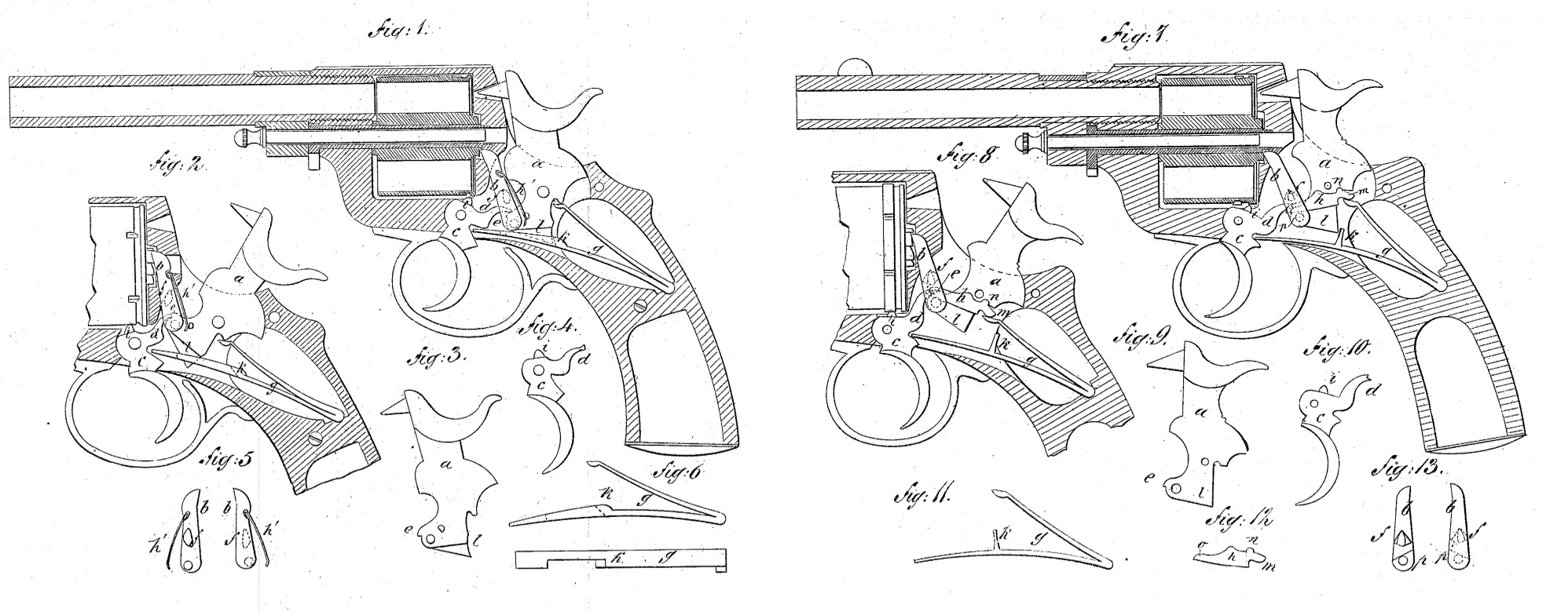
Figure 1 is a vertical section through the center of one revolver, with the hammer at half-cock. Fig. 2 shows a vertical section of the same, the hammer being at full-cock. Figs. 3, 4, 5, and 6 show separately each piece taken out of the lock. Fig. 7 is a vertical section through the center of another revolver slightly different from the first. Fig. 8 represents the same section again, but with the hammer brought to full-cock. Figs. 9, 10, 11, 12, and 13 show all the parts of the lock when taken to pieces.
Similar letters of reference indicate corresponding parts in all the figures.
In the accompanying drawings, a is the hammer, carried on a pivot made in one piece with the frame of the revolver. It is provided with a pawl, b, which causes the cylinder to revolve. The trigger c also has a projection, d, which passes between the lower part, e, of the hammer and a projection, f, under the pawl b.
The mainspring g is double-branched. Its lower branch acts directly upon the trigger, and its upper branch acts upon the hammer, either directly, as in Fig. 1, or it may be made to press against a small lever, h, as in Fig. 7, the said lever being so arranged as to act at the same time upon the pawl b in order to keep it in contact with the cylinder. By the use of lever h it becomes possible to do away with the small spring h’, Fig. 1.
The operation of the lock is as follows: When the trigger c is pressed back its projection d catches the projection f under pawl b, which, being pivoted on the hammer, brings it up to full-cock, while the cylinder is caused to revolve. As the trigger is pressed fully back the projection d escapes from the projection f, so that the pawl b and the hammer a become free and are brought down by the spring g, thus firing the cartridge. The cylinder is firmly held to its position, as usual, by the projection i on the trigger c while the cartridge is being fired. The trigger, when released from the pressure of the finger, is brought down to its first position by the action of the lower part of spring g. While that movement takes place the projection d of the trigger comes in contact with the top of projection f, and the pawl b is pushed back, so as to allow projection d to pass and catch again under projection f.
The lower branch of spring g is made with a catch, k, so that during its downward motion it presses upon a projection, l, of the hammer and brings it back to half-cock automatically. The action of lever h requires a few more explanations. As is seen in Figs. 7 and 8, the said lever is subjected at m to the pressure of the upper branch of spring g, and is thus kept in contact with the hammer at n. The parts in contact are so shaped as to allow a slight oscillation of the lever, the long branch o, Fig. 12, of which acts upon a small cam, p, Fig. 12, made with the pivot of the pawl d, which is thus constantly pressed against the cylinder. When the hammer is cocked by the thumb acting directly upon it the operation of the lock is altered slightly. In the case projection e of the hammer lifts up the projection d of the trigger, so that it reaches a small catch under projection e, as may be seen in Figs. 2 and 8. The trigger, when pulled back, releases the hammer, which is brought down by the spring g, and the operation continues then as before.
Having thus fully described our invention, we claim as new and desire to secure by Letters Patent–
In combination with the hammer, the main-spring, and the trigger having a projection d, arranged for operation as described, the pawl b, pivoted to the hammer and provided with a projection, f, against which the trigger, by its projection d, exerts a lifting action, and from which it subsequently escapes, and the trigger is allowed to return to its normal position by the yielding of the pawl, essentially as herein set forth.
EDOUARD BLED
JEAN WARNANT
Witnesses:
AUGUSTE CAUPIR,
EDWARD H. MACLEAN.