
US 226923
UNITED STATES PATENT OFFICE.
EMILE NAGANT AND LEON NAGANT, OF LIEGE, BELGIUM.
REVOLVING PISTOL.
SPECIFICATION. forming part of Letters Patent No. 226,923, dated April 27, 1880. Application filed September 24, 1879.
To all whom it may concern:
Be it known that we, EMILE NAGANT and LÉON NAGANT, both of Liege, in the Kingdom of Belgium, have invented a new Arrangement of Revolving Pistol, of which the following is a specification.
In this arm the following points are novel:
First. The bow of the trigger-guard serves as a spring-vise. It is applied in a novel manner, and forms a powerful lever, by which the mechanism may be taken to pieces or put together with great facility.
Second. The hollow space between the body of the revolver and the side plate, instead of being closed by a flange on one of those parts, is filled up by a separate piece of wood, metal, or other material fixed to the body or to the side plate. This arrangement simplifies very much the manufacture of the arm, and facilitates the cleaning of it.
Third. The axial stem of the cylinder or cartridge-chamber, as well as the extracting rod inclosed in it, are kept in their place by a new and very safe arrangement, very easy to manage. It consists of a piece placed in the head of the axial stem. The pressure of a spring forces a projection on this piece to enter a notch made in the body of the revolver.
Another projection from the same piece enters a notch in the extracting-rod. In the drawings similar letters relate to like parts in all the figures.
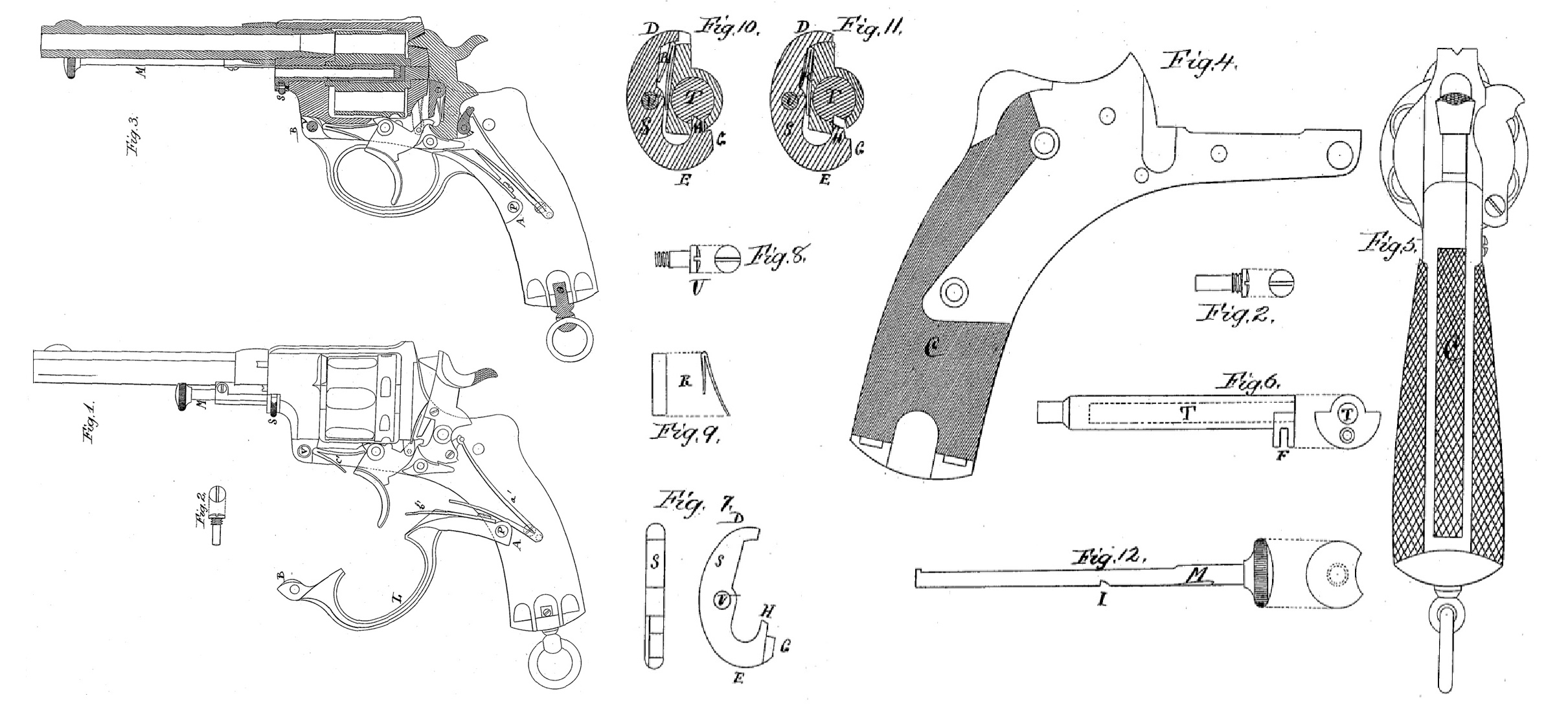
Figure 1 shows a revolver from which the side plate is removed, showing the internal mechanism. The bow of the trigger-guard L is open, leaving free the main striking-spring a’, the sear-spring l’, and the trigger-spring c’. Fig. 3 shows a revolver, also without the side plate, part of the arm being seen in section. The bow of the trigger-guard is closed. It cocks or places in tension the three springs above mentioned.
As shown in Figs. 1 and 2, the bow of the trigger-guard is fixed to the body by its two extremities-that is to say, at A upon a pivot, P, and at B by a screw, W, Fig. 2.
When the bow of the trigger-guard is open, as in Fig. 1, the springs are uncocked or relaxed, which allows of the removal by the fingers of all the small pieces of mechanism, which carry their own axes. The bow of the trigger-guard itself is easily taken out, as on removing the screw V it is left free and may be withdrawn from its pivot P. The two points of attachment of the bow of the trigger-guard being at a great distance from one another, the latter forms a powerful lever, which serves to cock or place in tension the springs for the putting together of the mechanism.
In our revolver the inner faces of the handle of the body and of the side plate are both without flanges and are flat, which simplifies the manufacture of the arm and facilitates cleaning the same. From this mode of construction there results an empty space in the handle of the arm between the body and the side plate. This space is filled with a separate piece of wood, metal, or any other material fixed to one of the plates by a screw or other means. Fig. 4 shows at C this piece fixed to the inner face of the side plate. Fig. 5 shows at C this same piece as seen from behind the handle of the revolver when the side plate is fixed to the body.
In our revolver the axial stem of the cylinder or cartridge-chamber, Fig. 6, has a luole, T, bored in it lengthwise to receive the extracting-rod. The head of this stem is slotted in its thickness. (See F, Fig. 6.) In this slot is placed the locking-piece S, Fig. 7, secured to the head of the stem by a screw-pivot, U, Fig. S, and pressed by a spring, R, Fig. 9. (See also Figs. 1 and 3.)
Fig. 10 shows the locking-piece S pivoting upon its axis. The part D of the said locking piece projects outside the head of the stem by reason of the pressure of the spring R. The part E of the locking – piece approaches the body of the stem. The projection G of the locking-piece enters a notch formed in the body of the revolver, and thus prevents the axial stem of the cartridge – chamber from coming out of its place. At the same time the projection H of the locking-piece passes into the hole T of the axial stem through a lateral opening, and enters the notch I of the extracting rod M, Fig. 12. The extracting-rod is thus held firmly in the axial stem.
In Fig. 1 the extracting-rod M is seen in place under the barrel of the revolver, and in closed in the axial stem of the cylinder or cartridge-chamber. Fig. 3 shows the extracting rod M withdrawn out of the stem and turned to the side of the barrel for the extraction of the cartridge-cases.
When it is required to draw out the extracting-rod and the axial stem of the cylinder or cartridge-chamber, the finger is placed on the part D of the locking-piece. (See Fig. 11.) This part D enters the head of the stem. The part E, on the contrary, moves away. The projections G and H, respectively, leave the notch in the body and the notch I in the extracting-rod, Fig. 11, which allows the extracting-rod to be drawn out of the stem and the stem out of the cylinder or cartridge-chamber and body.
We claim–
1. The combination of the trigger-guard level L, swiveled at P in the frame, bearing upon the mainspring near its pivotal point to compress the mainspring with, and serving to compress the minor springs in the lock, substantially as shown and described.
2. The combination of the frame made with flat interior surfaces with the separate piece as C, secured between the said flat interior surfaces of the frame, substantially as described.
3. The combination of the axial stem of the cylinder or cartridge-chamber and of the extracting-rod, hereinbefore described, composed as follows: a piece, S, secured in the head of the axial stem of the cylinder or cartridge-chamber, such piece being pressed by a spring, R, which forces a projection, G, of the said piece to enter a notch in the body of the revolver, and another projection, H, to enter a notch in extracting-rod M, as hereinbefore described.
EMILE NAGANT. L. NAGANT.
Witnesses:
N. CROWY,
GEO. STOCKWELL.