
US 140028
UNITED STATES PATENT OFFICE.
CHARLES FRANCOIS GALAND, OF PARIS, FRANCE.
IMPROVEMENT IN FRAMES AND STOCKS FOR REVOLVING FRE-ARMS.
Specification forming part of Letters Patent No. 140,028, dated June 17, 1873; application filed January 9, 1873.
To all whom it may concern:
Be it known that I, CHARLES FRANCOIS GALAND, of Paris, in the Republic of France, have invented a new Improvement in Revolving Pistol; and I do hereby declare the following, when taken in connection with the accompanying drawings and letters of reference marked thereon, to be full, clear and exact description of the same, and which said drawings constitute part of this specification, and represent in–
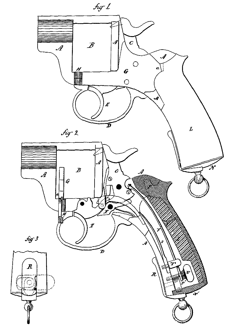
Figure 1 a side view; Fig. 2, a sectional side view; and in Fig. 3, a front edge view of the butt of the stock and frame.
This invention relates to an improvement in the construction of the frame, and manner of stocking pistols, particularly that class of pistols termed revolvers, the object being to readily expose all of the operative parts without detaching any of the said parts; and the invention consists in hinging one side of the lock-cover forward of the trigger-pivot, so as to open and expose the lock mechanism, combined with the breech chambered-out on its front side to cover the frame and spring, which, when in place, holds the first-named plate in position, the stock secured by a clamping device, all as more fully hereinafter described.
A is the frame; B, the chamber within which the cylinder is arranged; C, the hammer; D, the trigger-guard; E, the trigger. The other parts of the mechanism are shown in Fig. 2, but need no further reference, as they are no part of this invention. In one side of this frame the parts which support the sear, trigger, and hammer, are rigidly fixed. On the opposite side the plate G covers the same parts, the pivots of the sear and hammer extending through this plate, as seen in Fig.1. This plate is hinged to the frame at H, forward of the trigger, so that when turned up forward, as seen in Fig. 2, it will expose the operative mechanism of the arm. When closed, the two sides correspond. L, the stock, has a butt plate N extending up, and with a hook, P, to engage in a recess on the frame, as seen in Fig. 2. This is chambered out to cover the springs, and is locked to the frame at the butt by means of a lever, R., having a cam, P’ upon the inside, which turns with the said lever. When the said lever is turned down, as denoted in broken lines, Fig. 3, then the stock L may be removed and expose the springs; but, when the stock is in place and the lever R up, the cam P’ passes into a recess in the butt plate, as seen in Fig. 2, and holds the stock in position. On the plate A, a notch a is formed, as denoted in broken lines, Fig. 1, over which the stock extends, so that when the plate is turned down and the stock in place, the stock is the means for holding the plate in a closed position.
As a means for adjusting or removing the springs F S, I secure the spring S to the frame by means of a screw, T. Upon or within the head of this screw T the main-spring F lies, and below this head a thumb-screw, U, passes through the main-spring F into the frame. By means of the screw U the main spring may be readily adjusted, or, if desired, the two screws may be readily removed and the springs detached; and all the operative parts may be then taken from their pivots.
By this construction, the arm is readily cleaned or repaired, the usual difficulties in removing the parts being avoided, and no implements are required in the adjustment or removal of the parts.
I claim as my invention–
1. The plate G hinged to the frame forward of the trigger and covering the mechanism of the lock, combined with the stock L covering the spring, the said stock attached to the frame so as to secure the plate G, all substantially as set forth.
2. The screws T U, combined with their respective springs F S, for the purpose of securing and adjusting the said springs, substantially as set forth.
C. F. GALAND.
Witnesses:
JULES ARMENGAUD, Jr.
LEON DUEROYNE,