
US 119048
UNITED STATES PATENT OFFICE.
CHARLES B. RICHARDS, OF HARTFORD, CONNECTICUT, ASSIGNOR TO THE COLTS PATENT FIRE-ARMS MANUFACTURING COMPANY.
IMPROVEMENT IN REVOLVING FIRE-ARMS.
Specification forming part of Letters Patent No. 119,048, dated September 19, 1871.
To all whom it may concern:
Be it known that I, CHARLES B. RICHARDS, of Hartford, in the county of Hartford and State of Connecticut, have invented certain new and useful Improvements in Revolving Fire-Arms; and I do hereby declare the following to be a full, clear, and exact description of the same, reference being had to the accompanying drawing making part of this specification, in the several figures of which the parts are represented in their actual dimensions.
My invention relates to the apparatus for turning the rotating breech or the group of barrels, and to means for retaining and removing the cartridges or their shells. It consists in a guide-pin on the pawl, in combination with a guiding-surface on the pistol-frame, substantially as shown and hereinafter described, whereby the pawl, when acting on the ratchet-teeth, is prevented from thrusting the cylinder forward. It also consists in the combination with the ratchet of a shoe, shaped as described, to assist in preventing the cartridge-shells from slipping out of the chambers of the breech, and to fill the channel cut in the frame to permit the insertion and removal of the breech. It also consists in a peculiar fastening for the ejector-rod, hereinafter described.
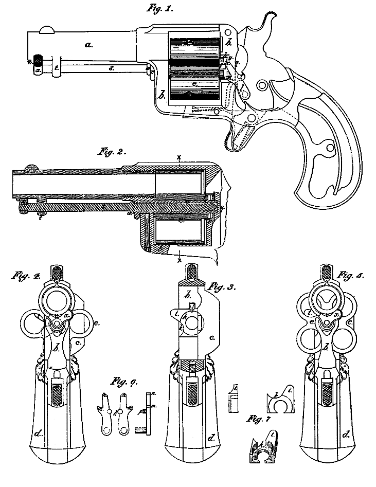
Figure 1 is a side elevation of the pistol with side cap and stock removed; Fig. 2, a longitudinal vertical central section of parts of the pistol; Fig. 3, a cross-section of the frame at X X; and Figs. 4 and 5 are end views of pistol as seen from the muzzle, showing the cylinder in two different positions. Figs, 6 and 7 are detail views of the pawl and the ratchet-shoe, respectively.
a is the barrel; b, the frame; c, the side cap of the frame; d, the stock; e, the revolving breech with its projecting ratchet f. This breech is made with four chambers bored through from front to rear. Its outside is deeply fluted between the chambers, and its position when the pistol is discharged is shown in Fig. 4; but when not in use the breech may be turned into the position shown by Fig. 5, so that the pistol becomes more compact. The frame d has a transverse channel, g, cut across it at the rear of the rotating breech. This channel is wide enough to permit the side wise insertion and removal of the breech, whose ratchet enters the channel. A shoe, h, of the peculiar shape shown in the three views of Fig. 7, fills that part of the channel g not occupied by the ratchet. This shoe has a wing, i, which projects far enough beyond the frame (see Figs. 3 to 5) to form a guard, which, in connection with the frame and the cap, prevents the cartridges from moving out of the breech backward, except at one point indicated by k, where the shoe and frame are cut away to permit the insertion and ejection of the cartridges and shells. l is the pawl for rotating the breech, and in the acting point which catches on the ratchet-teeth to produce the rotation. n is a prolongation of the pawl above the acting point m, arranged as and for the purpose now to be explained. It is desirable that when the hammer is at half-cock it shall be so little raised that the breech will have been turned by the pawl only very slightly; but with the usual form of pawl this position of the parts involves a difficulty, for, if the breech is rotated by hand for the purpose of loading or emptying the chambers, the lower teeth of the ratchet approach the pawl in a lateral direction in such a way that the inclined back surfaces of the said approaching teeth will, in passing the pawl, force it sidewise to an objectionable extent, I obviate this difficulty by providing the prong n above the acting point m, which prong is so shaped that when the breech is rotated by hand the pawl will be lifted–that is to say, be forced backward– by the action on the prong of the inclined back surface of that ratchet-tooth which has passed above the point m, (which in that position moves nearly parallel with the prong n,) instead of being forced back by the lower ratchet-teeth, which, if they should touch the pawl, would act on it nearly transversely and retard rotation. To prevent the action of the pawl from thrusting the cylinder endwise I provide on the side of the pawl a stud or equivalent projection, p, which bears on a vertical guiding-surface, q, made on the frame. This arrangement guides the acting point m in a nearly-vertical line, so that all tendency of the pawl to move forward is resisted by the guide q, instead of being transferred to the ratchet. The center-pin r, on which the breech e rotates, is hollow and receives a part of the ejector-rod s, which lies lengthwise beneath the barrel and extends nearly to the muzzle. This rod s passes loosely through a loop or guide, t, fastened to the barrel. By pulling the ejector-rod s length wise out of the center-pin and slanting it so that it may enter the breech-chambers as they are brought into line with the opening k the rod may be used to push out the cartridges or empty shells from the chambers. When the ejector-rod is not in use it should lie in its place under the barrel, and it is retained in this position by a projection, v, on the barrel near the muzzle. The head x of the ejector-rod lies back of this projection, and the said head is eccentric to the rod, so that when it is in the position shown in the drawing by full lines it is prevented from moving endwise by the projection v; but when the head x is turned into the position shown by dotted lines in Fig. 4, then the head will clear the projection and the rod may be drawn out from the center-pin. A collar, w, on the rod s, too large to pass through the loop t, prevents the loss of the rod. The shape of the head x, as shown in the drawing, is such that the lateral stiffness of the rods prevents the head from being so turned that the rod may be removed without some effort. This prevents its being accidentally turned.
Having thus explained my invention in a manner which will enable it to be carried into practice by one skilled in the art, what I claim, and desire to secure by Letters Patent, is–
1. The guide-pin p of the pawl, in combination with the guiding-surface q, when arranged substantially in the manner described, for the purpose set forth.
2. The ratchet-shoe h with its wing i, in combination with the transverse channeling the frame substantially as set forth.
3. The eccentric head x of the ejector-rod shaped substantially as shown, in combination with the projection v, for the purpose explained.
In testimony whereof I have hereunto set my hand.
C. B. RICHARDS.
Witnesses:
E. J. MURPHY,
GEO. F. STONE.