
US 129334
UNITED STATES PATENT OFFICE.
JOHN GORDON, OF SAN FRANCISCO, CALIFORNIA.
IMPROVEMENT IN REVOLVING FIRE-ARMs.
Specification forming part of Letters Patent No. 129,334, dated July 16, 1872.
SPECIFICATION.
To all whom it may concern:
Be it known that I, JOHN GORDON, of San Francisco, San Francisco county, State of California, have invented Improvements in Fire-Arms; and I do hereby declare the following description and accompanying drawing are sufficient to enable any person skilled in the art or science to which it most nearly appertains to make and use my said invention and improvement without further invention or experiment.
The object of my invention is to provide an improvement in fire-arms, by the use of which I am enabled to discharge a number of shots from a gun with great rapidity without going through with the numerous movements necessary for ordinary breech-loading or magazine guns.
In the present case my invention is shown as applied to a revolving-chambered gun; and it consists in the use of a series. of levers and springs combined, as hereinafter described, so that the hammer can be raised and the gun be made ready to fire by pressing the butt of the stock against the shoulder. When the trigger is pulled the hammer falls and discharges a chamber, and at the same instant another spring is released, which again raises the hammer to the position of full-cock, and also operates the mechanism for revolving the cylinder, so that the next chamber is brought into position. By again pressing the butt of the piece against the shoulder the firing-spring is again set, and all the chambers can thus be discharged without removing the piece from the shoulder.
Referring to the accompanying drawing for a more complete explanation of my invention–
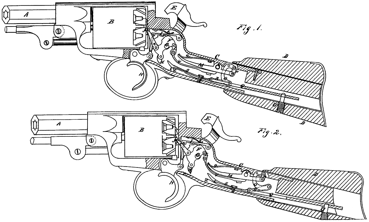
Figure 1 is a side elevation, partly in section, of the piece, showing the mechanism set ready to be discharged. Fig. 2 is a side elevation, partly in section, showing the position of the mechanism after the discharge.
A is the barrel of a gun. B is the revolving chamber; C, the small of the stock, and D the butt-piece. This butt is hollowed out so as to just slide over the small of the stock, and it has a small movement back and forward for the purpose of operating the mechanism, which is constructed as follows: E is the hammer. F is the tumbler, mounted upon the tumbler-shaft G, which carries the hammer at its outer end. H is the trigger, which is connected with the dog or catch I by a bar or link, J, as shown. The spring K holds the catch down so that it falls into a notch in the top of the tumbler, and thus retains the hammer at full-cock when the spring is set. The main-spring V has its front end connected with the rear of the tumbler by a link, L. The rear end of the main-spring is secured to the lever M, so that it ordinarily lies closely against it; but when the gun is ready for firing its front end is separated or forced away from the lever, as shown in Fig. 1. The elasticity of this spring returns it to its place against the lever when the trigger is pulled and the tumbler released, so that the hammer falls. The lever M has its fulcrum at N, and its rear end is connected with the curved or knee-lever O by a link, P. The lever O is in turn connected with the operating-bar Q by a link, R. From the front of the bar Q a plate or spring, S, extends forward, and is provided with a catch, t, near its front end. The bar Q extends back through the small of the stock, and is secured to the butt-piece D by a screw or bolt, U.
The operation will be as follows: The gun being in its ordinary state-that is, not set for firing-the parts will stand in the position shown in Fig. 2. The main-spring V will be against the lever M, which will have its front end depressed, as shown, by the spring a, and by this means the tumbler F will be drawn down so that the hammer will stand at full-cock and the catch I will be in position to hold it there when set. The parts being in position, the gun is brought to the shoulder and the butt D pressed firmly against it. This causes the bolt U to force the bar Q forward, thus carrying the spring S forward, until the catch t is held by the lug c, as shown at Fig. 1. At the same time one arm of the knee-lever o is forced forward by the bar Q and the other arm is drawn downward, thus depressing the rear end of the lever M and elevating its forward end. As the tumbler is held in place by the catch I this movement of the lever M separates it from the spring V and thus gives it the necessary tension to force the hammer down when released. The trigger being pulled, the hammer falls upon the cap, which is placed upon the nipple, and thus the gun is discharged. At the same instant a lug, d, at the lower part. of the tumbler, is carried backward by its rotation so as strike the spring S and release the catch t. This allows the spring a to act upon the lever M and depress the forward end to its first position, at the same time raising the hammer to the position of full-cock. The bar Q and catch t are also drawn back by the action of the levers. The cylinder B is revolved in the ordinary manner by a pawl, e, which is pinned to one side of the tumbler, and operates upon a ratchet, f, at the rear of the cylinder. When the hammer falls the rotation of the tumbler carries the pawl down one tooth of the ratchet, and when the hammer flies back to the position shown the pawl forces the cylinder to revolve. By this mechanism the whole operation of firing is rendered simple and rapid, the only movement necessary being the pressure of the butt against the shoulder to set it and the pulling of the trigger.
I do not wish to confine myself to the special mechanism here shown, as the devices will be modified when applied to the Henry, Spencer, and other repeating or magazine arms; but
What I do claim, and desire to secure by Letters Patent, is–
1. The bar Q, and the spring S with its catch t, in combination with the movable butt D for setting and holding the mechanism, substantially as herein described.
2. In combination with the operating-bar Q and butt-piece D, I claim the levers M and O and the spring V, the whole constructed to operate substantially as described.
3. The trigger H, connecting-bar J, holding-lever I, and tumbler F, when constructed and operated substantially as herein described.
4. The lug d operated by the tumbler F for releasing the spring S substantially as and for the purpose above described.
5. I claim the spring a in combination with the lever M and main-spring W, to return the parts to their position when released, substantially as and for the purpose above described.
6. The combination of devices for automatically rotating the cylinder, consisting of the levers M and O, springs a and V, tumbler F, and pawl e operating the ratchet f, substantially as and for the purposes above described.
7. In combination with the sliding butt D, I claim the mechanism, substantially as herein described, whereby the main-spring is made operative when the butt is pressed forward.
In witness whereof I have hereunto set my hand.
John Gordon. [L. S.]
Witnesses:
GEO. H. STRONG,
GEORGE WUEST, Jr.