
US 75016
United States Patent Office
GEORGE HOLMAN, OF WATERVILLE, NEW YORK.
Letters Patent No. 75,016, dated March 3, 1868
IMPROVEMENT IN REVOLVING FIRE-ARMS.
The Schedule referred to in these Letters Patent at taking part of the same.
TO ALL WHOM IT MAY CONCERN:
Be it known that I, GEORGE HOLMAN, of Waterville, in the county of Oneida, and State of New York, have invented a new and useful Improvement in Fire-Arms; and I do hereby declare that the following is a full, clear, and exact description thereof, which will enable others skilled in the art to make and use the same, reference being had to the accompanying drawings forming a part of this specification.
This invention relates to a new and useful improvement in fire-arms of that class which is provided with a revolving many-chambered cylinder.
The invention has for its object, first, the combining in one piece or weapon of a rifle and smooth-bore, (shot-gun,) in such a manner that either may be used at the will of the hunter or sportsman; second, the rotating of the cylinder from the hammer by a means simple and efficient, and less liable to get out of repair than the mechanism usually employed for such purpose; third, in a novel arrangement of the cylinder, method of securing it in its frame, whereby it is firmly held in position, and permitted to rotate under the movement of the hammer, with but little friction, and consequently without subjecting the actuating parts to any unnecessary or undue wear and tear. In the accompanying sheet of drawings–
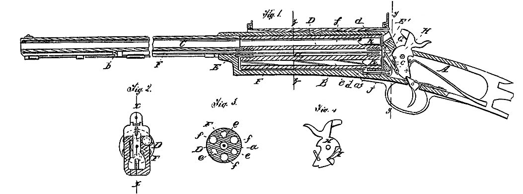
Figure 1 is a longitudinal central section of my invention, taken in the line x x, fig. 2.
Figure 2, a transverse section of the same, taken in the line y y, fig. 1.
Figure 3, a detached transverse section of the chambered cylinder.
Figure 4, a detached side view of the hammer.
Similar letters of reference indicate corresponding parts.
A, represents a portion of the stock of the fire-arm, the metal portion to which the wooden portion is attached, and B is a metal frame connected with A, and forming a part of the same piece, C is a barrel, fitted in the outer end of a frame, B, and secured therein by a screw or other suitable means. In the frame B the chambered cylinder D is fitted, so as to rotate freely. This cylinder has a hole, a, drilled entirely through it at its centre, and in the ends of the hole a there are screwed plugs E E’, which are drilled centrally to work upon a rod, F, the inner end of which is fitted in a hole in the rear end of the frame B, and the outer end fitted against a stop, b, secured to the under side of the barrel C, as shown in fig. 1. The plugs E E’ form the journals of the cylinder D, the hole a, in said cylinder, being too great in diameter to allow the cylinder to come in contact with rod F, as is also shown in fig. 1.
By this arrangement the cylinder D is allowed to rotate freely and with but little friction, and at the same time, owing to the length of rod F, the latter is allowed sufficient elasticity or spring to admit of its outer end being readily fitted within or drawn out from the stop b, so that the rod F may be withdrawn, and the cylinder taken from frame B when required, without any difficulty whatever. The plug E’, at the inner end of cylinder D, is provided with ratchet teeth, with which a pawl, G, engages, said pawl being attached to one side of the hammer H, and having a spring, c, connected with it, which spring has a tendency to keep the pawl engaged with the ratchet, (see fig. 1.)
To the front side of the hammer H there is attached a spring, I, which projects upward and outward from the hammer, and acts when the hammer is drawn back against a bont lever, J, which serves as a stop for the cylinder D, the latter having a series of holes, d, in its exterior to receive the front end of the bent lever which holds the chambers e f of the cylinder D in line with the bore of the barrel C. It will be seen, therefore, that each time the hammer H is drawn back, the springe actuates the bent lever J, and throws it out from a hole, d, in the cylinder D, so that the pawl G. may turn the plug E, and consequently the cylinder D, and bring a succeeding chamber of the cylinder in line with the barrel C, a spring, ax; throwing the lever J in the holes d. By having the spring I attached to the front side of the hammer H, a strong and durable cylinder-stop actuating mechanism is obtained.
The chambers e f of the cylinder D are all charged at the rear end, if cartridges K be used. The chambers e are rifled, and f are smooth, the former being designed for balls, and the latter for shot. The bores of both these chambers are smaller in diameter than the bore of the barrel C, it being designed to have the cylinder D of sufficient length to admit of the ignited powder acting sufficiently long upon the ball or shot to insure a requisite force or propelling power upon the same. The chambers e f have an alternate position in cylinder D, as shown in fig. 3.
Having thus described my invention, what I claim as new, and desire to secure by Letters Patent, is–
1. The plugs E. E’ in the ends of the central bole a of cylinder D, in combination with the rod F, on which said cylinder is fitted, all arranged substantially as and for the purpose set forth.
2. The providing of the cylinder D with alternate rifled and smooth-bores e f, smaller in diameter than the bore of barrel C, substantially as and for the purpose specified.
3. The attaching of the spring I, which operates the stop-lever J to the front side of the hammer H, for the purpose of insuring strength and durability.
GEORGE HOLMAN,
Witnesses:
H. P. BIGELOW,
WM. B. GOODWIN.