
US 65510
United States Patent Office.
MATILDA C. ROOT AND ELISHA COLT, OF HARTFORD, CONNECTICUT, AND HARRIS COLT, OF NEW YORK, N. Y., EXECUTORS OF E. K. ROOT, DECEASED, ASSIGNORS TO COLT’S PATENT FIRE-ARMS COMPANY, OF HARTFORD, CONNECTICUT.
Letter Patent No. 65,510, dated June 4, 1867.
IMPROVEMENT IN REVOLVING FIREARMS.
The Schedule referred to in these Letters Patent and making part of the same.
TO ALL WHOM IT MAY CONCERN:
Be it known that E. K. Root, deceased, late of Hartford, in the county of Hartford, and State of Connecticut, did inventeertain new and useful Improvements in Repeating Fire-Arms, of which the following is a full, clear, and exact description, reference being had to the accompanying drawings, and to the letters of reference marked thereon.
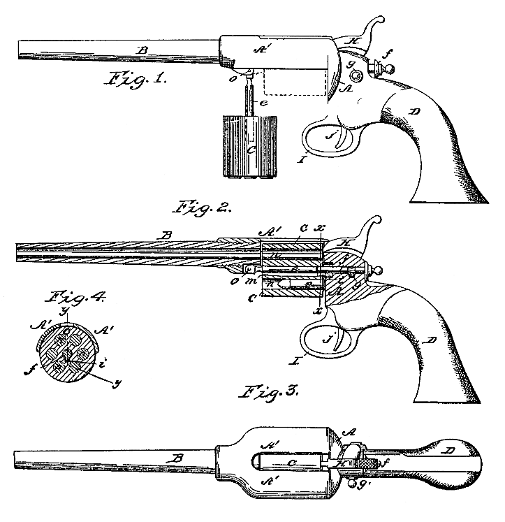
Figure 1 is a side elevation of a repeating pistol embracing the invention made the subject of this application.
Figure 2 is longitudinal sectional elevation of the same.
Figure 3 is a top view of the same; and
Figure 4 is a cross-section at the line x x of fig. 2.
In the several figures the same part will be found designated by the same letter of reference.
Previous to this invention it has been customary to so construct and adapt the chambered breech-block or rotating cylinder as to render it necessary to introduce the cartridges to be fired therefrom always at the same end of the cartridge-chamber, and in the use of fixed ammunition or metallic cartridges this method of construction has rendered it necessary to employ some means of extracting the empty cases of the exploded cartridges before the same chambers could be reloaded. To dispense with this necessity, and accomplish the reloading without having to previously extract the empty cartridge cases, is the object of the first part of this invention, which consists in the employment of a reversible breech-block or cylinder which can be arranged with either end adjacent to the barrel, and the chamber of which can he loaded from either direction, so that after the cartridges have been exploded the cylinder may be removed, the empty cases be forced out by the introduction at the opposite ends of the chambers of fresh cartridges, and the reloaded cylinder bé then replaced in a reversed position between the barrel and hammer, as will be hereinafter more fully described.
In that class of fire-arms to which this invention relates, it is a great desideratum to embody some means of easily effecting the removal and replacement of the cylinder, to accomplish which object is the aim of the second part of this invention, which, to this end, consists in hanging or arranging the cylinder on two centres or base-pieces, one extending from the breech-plate into the rear clad of the cylinder, and the other from the barrel or forward portion of the frame into the front end of the cylinder, and being pivoted or hinged to said rear portion of barrel (or forward part of frame) so that when the rear base-pin is withdrawn the cylinder can swing out from the frame on the hinged base-pin, and then be slid off of said hinged basc-pin, as will be presently more fully explained.
To afford a stronger frame in proportion to the material employed, and at the same time permit the removal in a downward direction of the cylinder from the frame, is the object of the third part of this invention, which consists in so forming the frame as to constitute, virtually, straps or bands extending from the breech-plate to the rear end of barrel, running almost or quite wholly above the axis of the cylinder, and on each side of the chamber which is in line with the barrel, as will be hereinafter more fully explained.
To make more clear the several features of this invention, and enable those skilled in the art to make and use a fire-arm embodying this invention, the following full description is given, referring by letters to the several parts of the pistol illustrated in the drawings.
A A’ represent the frame; B the barrel; D the stock; H the hammer; I the guard, and j the trigger of a repeating pistol embracing my improvements. C is a many-chambered rotary cylinder, the chambers n of which are bored through and through. The barrel B has its rear-end scy owed into the frame A’, and the cylinder C is adapted to turn on base-pins, e f, in such manner that its chambers, n, may in succession be brought in line with the bore of the barrel B to be fired. It is proposed to effect the rotation of the cylinder C through the medium of the rear base-pin f, (by means of any suitable actuating mechanism operating on the said base-pin,) and for this purpose the forward end of said pin f is made to project into the central hole or bore of the cylinder, and is provided with a short feather or key, i, which fits, in the spline or longitudinal groove, m, in such manner as to clutch the cylinder to the end of said pin f and cause the cylinder always to rotate with the pin f. The cylinder C is further sustained by (and rotates upon) another pin or stud, e, which projects or extends into the forward end of the central bore of the cylinder, and to a much greater extent than pin f, and which pin e is hinged at o to the forward portion of the frame in such manner as to be capable of swinging down, as seen at fig. 1, (to permit the removal and replacement of the cylinder, as will be presently explained.) Tho chambers n of the cylinder are bored through, of a cylindrical form, and both ends of the cylinder, is will be seen, are of the same size and shape precisely, and the groove m being run through the whole length of the cylinder, it is obvious that said cylinder may be placed on its centres or base-pins with either end next to the barrel. As before stated, the object of having the cylinder this reversible is that the cylinder may be loaded from either end, as will now be explained.
Suppose the chambers m to have been loaded with the ordinary flanged cartridges. (as seen at p, fig 2,) and the said cartridges to have been exploded. Now to reload the chambers (with the same kind of cartridges,) the catch-pin g is pulled out so that the base-pin f may be drawn back, (as seen at fig. 1,) whereby the rear end of cylinder C is left unsupported. Said cylinder and its base-pin e are now swung down and away from the frame A A’, as seen at fig. 1, and the cylinder removed entirely from the arm (with the empty cartridge cases sticking in its chambers.) Loaded cartridges are now forced or pushed into the opposite ends of the chambers n, (in the direction indicated by red arrows, fig. 1.) forcing out the empty cases, and the cylinder is placed again on its pin e with that end next to the barrel which was before next to the breech-plate and hammer. The cylinder is swung back into line with the barrel and the pin f pushed in and locked (longitudinally) by the catch-pin g, when the arm is ready to be again fired. The peculiar shape of the frame is clearly illustrated in the drawings, where it will be seen that in lieu of the breech-plate or rear portion being united or connected to that portion into which the rear end of the barrel is screwed by means of bands running along above and below the cylinder, the frame is all open under the cylinder, and open directly over the cylinder, the portions A’ (see figs. 1, 3, 4) running along above the level of the base-pins and each side of the chambers in line or nearest in line with the barrel. By this form of frame it will be seen that the stock or material relied on to prevent the severance of the forward from the rear portion of the frame (by the concussion of the discharge,) is arranged in the most advantageous manner, since it extends in parallel straps, so to speak, running directly adjacent to the chamber being filled, and from the rear end of the barrel to that part of the breech-plate which receives the recoil of the charge. By this disposition of the stock or material of the frame the same may be made extremely light, and at the same time sufficiently strong. Another great advantage of the form of frame shown is, that it permits the removal of the cylinder downward or away from the lower part of the frame (when held in the hand in a natural position for the use of the arm.) And it will be understood that this feature of the invention is applicable, with the same advantages as here ascribed to it, to other arms not having the cylinder hung in the manner here described, or made to reverse in loading, as hereinbefore set forth.
It will be seen that by hanging the cylinder C on a hinged pin, e, as shown and described, (which extends nearly through it,) and having its rear end sustained by a pin, f, held laterally in a bearing, as set forth, the cylinder may be removed and replaced with great facility, while the pin f has to be moved only a short distance longitudinally, and that there are no other parts disconnected in the removal of the cylinder. And it will be understood that this feature of hanging, the renovable cylinder on the hinged base-pin in a solid frame, may be employed with advantage in an arm, not embracing the other features of invention hereinbefore described, and that the hinged pin may be employed in connection with a frame so constructed that the said pin would have to swing (with the cylinder) out from the side of the frame in lieu of downward, as herein set forth. In the application of this feature of the present improvements to a pistol in which the cylinder was not reversible, the pin e would be very convenient as a device or means for forcing or pushing out the empty cartridge cases.
It will be understood that the first feature of my invention, which really rests on the idea of an arm so constructed that its removable breech-block, a cylinder may be loaded and reversed in the frame, as hereinbefore set forth, may be employed under a great variety of modifications. In lieu of so forming the cylinder as to have it rotated by the rear base-pin, as described, it may be formed with a ratchet in each end, and be turned directly by the actuating pawl or “hand’ of the pistol, or the cylinder may be turned by hand without departing from the spirit of the invention covered by this first feature as characteristic.
Having fully explained the invention so that those skilled in the art can understand the several features of improvement and make and use a fire-arm embracing them, what is claimed as new, and desired to be secured by Letters Patent, is–
1. The employment, in combination with a removable breech-block or cylinder, of a vibratory base-pin, substantially as and for the purpose set forth.
2. The employment, in combination with a rotatory base-pin, of a cylinder bored through, when the whole is so constructed and arranged that the cylinder may be placed on the said base-pin and engage there with either end forward, as and for the purpose set forth.
3. The employment, in connection with stock, barrel, and a swinging cylinder, of a frame A’, of the shape substantially as described, so as to permit the removal and replacement of the cylinder in the manner set forth.
In testimony whereof we have hereunto set our hands and seals as executors of the last will and testament of E. K. Root, deceased.
MATILDA C. ROOT, [L. S.]
ELISHA COLT, [L. S.]
HARRIS COLT. [L. S.]