
US 21054
UNITED STATES PATENT OFFICE.
E. A. RAYMOND AND C. ROBITAILLE, OF BROOKLYN, NEW YORK, ASSIGNORS TO THEMSELVES, J. B. RICHARDS, AND T. K. AUSTIN..
IMPROVEMENT IN REVOVING FIRE-ARMS.
Specification forming part of Letters Patent No. 21,054, dated July 27, 1858.
To all whom it may concern:
Beit known that we, Edward A. Raymond and Charles Robitaille, of Brooklyn, in the county of Kings and State of New York, have invented, made, and applied to use certain new and useful Improvements in Repeating Fire-Arms; and we do hereby declare that the following is a full, clear, and exact description of the construction and operation of the same, reference being had to the annexed drawings, making part of this specification, wherein—
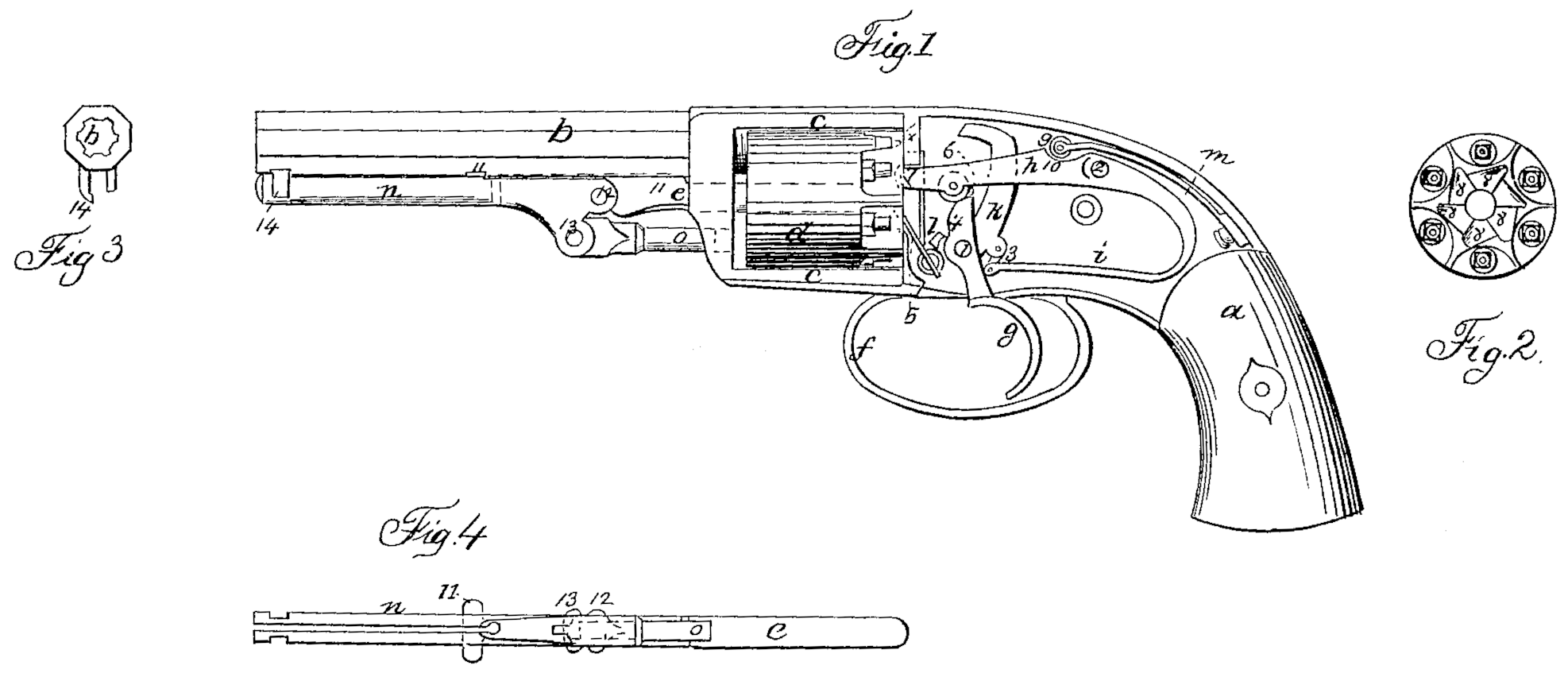
Figure 1 is a side elevation of our improved fire-arm with the cap-plate removed. Fig. 2 is an elevation of the breeches or chambers at the rear end. Fig. 3 is an end view of the barrel and latch receiving the loading-lever, and Fig. 4 is an inverted plan of said loading-lever and the parts attached.
Similar marks of reference denote the same parts.
In Letters Patent granted to C. S. Pettengill on 22d July, 1856, a repeating-arm is shown in which the chambers are revolved by a lever having a locking-pin at the end thereof, which, projecting into a hole at the rear of the chambers each successive discharge, holds the breech or chamber to be fired properly in line with the barrel, and in moving this lever a separate and detached mainspring is strained to discharge the hammer.
Our invention is an improvement on the aforesaid patent of Pettengill, and relates to a manner of working the said mainspring and lever, so as to perform all the functions required of them; also, to a manner of causing the end of the lever itself to lock and hold the chambers with the proper one exactly on the line of the barrel, thereby dispensing with the hinged locking-pin of Pettingill, which is found practically to be unreliable, because it often becomes wedged improperly into the rear of the chambers, particularly when the parts become fouled by the explosion.
In the drawings, a is the stock, b is the barrel, connected together with the straps c, between which the chambers d revolve on the center-pin e. f is the trigger guard, and g is the trigger on the pin 1. h is the lever to revolve the chambers, set with an elongated hole over the fulcrum 2, and formed as a part of the mainspring i, which is connected by the bridle 3 to the hammer k, moving on the pin 1. l is the sear of the hammer, and 5 is a spring talking into the recesses 8 of the chambers to prevent them being revolved in the wrong direction. On pulling the trigger g the upper part, 4, takes the roller 6 on the lever h, elevating said lever, and the point 7 thereof, taking one of the recesses 8, gives a partial rotation to the chambers, and as the lever h comes up into the position shown in Fig. 1 the chambers become blocked by the end of said lever, so that the chamber to be discharged is on the line of the barrel b, because the shape of the recess 8 is triangular, as seen in Fig. 2, and the end 7 of the lever h rising vertically in the line shown by the dots in Fig. 2, when the said part 7 reaches the apex of said triangular recess there can be no more motion of the chambers either way so long as said lever h is fully elevated. In the act of using the lever h the opening between the said lever and its mainspring i has been increased, so that the moment said lever h reaches its extreme elevation the trigger g disengages the sear l, and the spring i, through the bridle 3, propels the hammer k and explodes the cap and the chamber which is on the line of the barrel b, an opening being provided in the recoil-shield x for the passage of the end of the hammer k. Upon releasing the trigger g the spring m comes into operation, which causes the lever h to descend, and the roller 6, passing down the part 4, causes the trigger g to move forward, and the end 7 of the lever h slides down the incline from one recess 8 to the next, the elongated hole for the pin 2 allowing of this motion, and then the roller 9 on the end of the spring m, rolling down the incline 10 on the lever h, causes the end 7 to be projected into the next recess 8, and the spring i, moving with the lever h, draws back the hammer k, the sear l falls into its notch on the tumbler of said hammer, and the parts are ready for use, as before.
The pin e is held in place by means of a spring, 11, attached at one end to said pin e and at the other end provided with a crosspiece, and said spring occupies a parallel recess in the under side of the barrel b, and the end of said spring, taking against the side of a cross-groove in said barrel or a projection thereon, forms a resistance to keep said pin e in place while the lever in and rammer o are being used to ram the charges in the chamber d. 12 is the fulcrum of said lever n, and 13 is the joint-between the lever in and rammer. By raising the spring 11 out of the slot the center-pin e can be withdrawn for removing the chambers d, and there are no separate screws or pieces that are liable to be lost.
The lever n is of a length to extend as far as the end of the barrel b, and is made with a split in its center, so as to form a double spring, and the sides of this lever n are notched to fit the latch 14, (see Fig. 3,) so that when pressed into said latch the sides of the lever n, spring together, and when said lever is to be turned down for use the grasping of the same between the fingers and thumb compresses the sides and disconnects the lever from the latch.
We do not claim any part of the invention of the said Pettengill secured by the aforesaid patent; but
What we claim as our invention, and desire to secure by Letters Patent, is—
1. The manner herein specified of controlling the motions of the lever h and spring i by means of the spring m, roller 9, and incline 10, as and for the purposes described and shown.
2. Locking the chambers d by the end lever, h, taking the triangular recesses 8 in the rear of the chambers as said lever completes its upward movement, for the purpose and as specified.
In witness whereof we have hereunto set our signatures this 5th day of June, 1858.
EDWARD A, RAYMOND.
CEHARLES ROBITAILLE.
Witnesses:
Lemuel W. Serrell,
Thomas G. Harold.