
US 20765
UNITED STATE PATENT OFFICE.
F. D. NEWBURY, OF ALBANY, NEW YORK, ASSIGNOR TO R. V. DE WITT, JR. OF SAME PLACE.
IMPROVEMENT IN REVOLVING FIRE-ARMS.
Specification forming part of Letters Patent No. 20,765, dated June 29, 1858.
To all whom it may concern:
Be it known that I, Frederick. D. Newbury, of the city of Albany, State of New York, have invented certain Improvements in the Construction of Fire-Arms; and I declare the following specification, with the drawings hereto attached as part of the same, to be a full and perfect description of my invention, which, although intended principally for application to that class of arms known as “revolvers,” is also capable of use with ordinary guns and pistols.
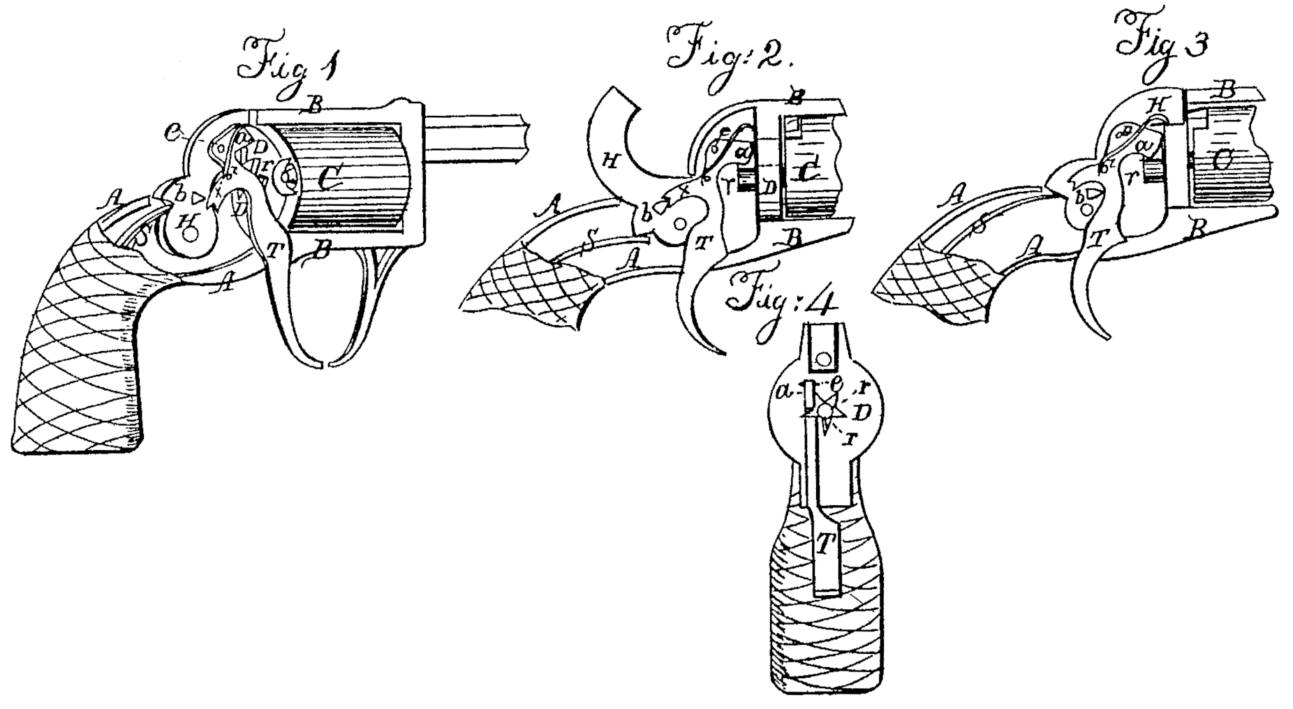
Figure l is a perspective view of a revolver-pistol, with a part of the outer casing removed to show the mechanism of the piece. Figs. 2, 3, and 4 are diagrams intended to show the positions of the mechanism at different stages in the operation of the piece.
Similar letters in all the figures denote the same parts of the piece.
AA is the skeleton stock-framing of a pistol expanded into a frame, B, to hold the usual revolving cylinder, C. This cylinder turns upon axles at each of its ends, the rear one passing through the back-bar of the frame, or what is called the “face-plate,” D, (being a disk equal in diameter to the cylinder,) behind and against which it carries the ratchet-wheel r, firmly attached to it, (the axle.) By this wheel the cylinder C is turned around through the action of the trigger T. This trigger, shaped as shown in the drawings, is pivoted to the frame at e, near its top, and has projecting from it forward a limb, a, which is fitted to conform to the spaces between the teeth of the wheel r, (see Figs. 1 and 4,) so that while the trigger is held firmly in position of Fig. 3 the wheel shall be blocked and held immovable. This limb also serves by a ratchet-pawl movement to turn the wheel r. From the back of the trigger another limb, x, projects to the rear, and is terminated by a small notch or nick. This limb operates the hammer H. by means of a pin, b, inserted into its side above its axis, the upper edge of the limb lying under the pin before the trigger is drawn, as shown in Fig.1.
The operation of the piece is as follows: The cylinder being loaded and capped and the machinery standing in the position as shown in Fig. 1, a pull upon the trigger, pressing the upper edge of the limb x against the pin b, will raise the hammer until the front end of the pin, which is fitted for that purpose, drops into the notch at the end of the limb, cocking the piece. A further pull upon the trigger will disengage the pin from the notch, and the hammer will be driven down by the spring S upon a cone of the cylinder, the pin passing under the limb x, as shown in Fig. 3. When the trigger is in the position of Fig. 1 the lower edge of is front limb, a a, rests upon the upper edge of a tooth of the wheel r, and as the trigger is drawn back the descent of the limb turns the wheel, and with it the cylinder; and when the trigger is drawn back to its fullest extent the limb a, fitting snugly against the faces of two adjacent teeth, holds the wheel from moving during the descent of the hammer, preventing the deviation of the chamber of the cylinder from the range of the barrel at the moment of firing. This will be seen in Fig. 4, which is a view of the ratchet-wheel and trigger, taken at the back edge of the face-plate D, looking toward the butt of the piece, the plate D being considered transparent to slow the mechanism behind it. The piece being fired and the trigger released, it (the trigger) is thrown forward by a spring, z, when the limb x passes down over the pin b, the end of the pin being beveled with an upward slope and the end of the limb beveled with a downward slope to permit the easy passage of the one over the other, aided by the elasticity of the trigger, and the parts take their place, as in Fig. 1. At the same time the limb a passes up along the tooth of the wheel r, against which it lies until it springs over its upper edge, where it rests, ready upon the next pull of the trigger to act upon that tooth. While this last operation is going on the cylinder is held from revolving by the pressure of the hammer, which lies upon one of the cones. The piece is now ready for a repetition of the firing.
The wheel r has the number of its teeth to correspond with the number of chambers in the cylinder, and the proportions of the limbs a and x and place of pin b are graduated in reference to the extent of the sweep of limb a in moving the cylinder.
It must be noted that it is not necessary to stop the movement of the trigger in order to cock the hammer, as shown in Fig. 2; but the full sweep of the trigger may be given at once, and so the chambers be discharged rapidly in succession by quick pulls of the trigger.
What I claim, and desire to secure by Letters Patent, is—
1. The trigger T, formed, fitted, and operating as described, for the purpose of cocking the hammer, revolving the cylinder, holding the cylinder in the act of firing, and firing the piece.
2. The combination of hammer, its pin b, the trigger, and the ratchet-wheel, formed and arranged substantially and for the purposes set forth in this specification.
F. D. NEWBURY.
Witnesses:
E. J. Miller,
Richd, Varick De Witt.