
British 86
LETTERS PATENT to Edward IIaslewoo.1, of Tufuel Park, Hollo-way, in tlie County of Middlesex, for the Invention of “ Improvements in Fire-arms and Projectiles.”—A communication.
Sealed the 9th March 1853. and dated the 19th January 1853.
PROVISIONAL SPECIFICATION left by the said Edward llaslewood at the Office of the Commissioners of Patents, with his Petition, on the 12tli January 1853.
I, Edward Haslewood, of Tufnel Park, Holloway, in the County of Middlesex, do hereby declare the nature of the said Invention for “ Improvements in Fire-arms and Projectiles to be as follows.
This Invention has for its object improvements in that class of fire arms which are loaded at the breech, and also in the projectiles or balls used therewith. The improvements in the fire-arms consist of surround ing the cylinder in which the charging chambers are formed with a metal band, which when acted on by an excentric tightly embraces the cylinder, and forces it up against the end of the barrel. The charging chambers or breeches are each made with a shoulder, the outer diameter being larger than the inner diameter, and it is slightly bell-mouthed. The ball or projectile is ca^t with an enlargement or ring at one end, which fits into the larger diameter of the charging chamber. The smaller diameter of the ball enters the smaller diameter of the charging chamber or breech, and when the whole of the charging chambers are charged with powder and balls the cylinder is introduced into a metal ring or hoop, which being tightly contracted by a screw will cause all the balls to be tightly compressed within their respective charging chambers or breeches. The bore of the barrel is somewhat smaller than those of the smaller diameter of the breech, and the inner end of the barrel is formed to enter into the bell mouth of the breech. The projecting ring on the ball will consequently be tightly pressed between the end of the barrel and the shoulder in the charging chamber or breech, and when discharged the projecting ring of metal on the ball is left in the breech, the other part of the ball being driven by the force of the powder through and separated from the ring of projecting metal, which, as before explained, was cast with and formed part of it.
SPECIFICATION in pursuance of the conditions of the Letters Patent, filed by the said Edward Haslewood in the Great Seal Patent Office on the 12th July 1853.
TO ALL TO WHOM THESE PRESENTS SHALL COME, I,
Edward Haslewood, of Tuihel Park, Holloway, in the County of Middlesex, send greeting.
WHEREAS Her most Excellent Majesty Queen Victoria, by Her Letters Patent, bearing date the Twelfth day of January, in the year of our Lord One thousand eight hundred and fifty-three, in the sixteenth year of Her reign, did, for Herself, Her heirs and successors, give and grant unto me, the said Edward Haslewood, Her special licence that I, the said Edward Haslewood, my executors, administrators, and assigns, or such others as I, the said Edward Haslewood, my executors, administrators, and assigns, should at any time agree with, and no others, from time to time and at all times thereafter during the term therein expressed, should and lawfully might make, use, exercise, and vend, within the United Kingdom of Great Britain and Ireland, the Channel Islands, and Isle of Man, an Invention for “ Improvements in Fire-arms and Projectiles,” communicated to me from abroad, upon tbe condition (amongst others) that I, the said Edward Haslewood, by an instrument in writing under my hand and seal, should particularly describe and ascertain the nature of the said Invention, and in what manner the same was to be performed, and cause the same to be filed in the Great Seal Patent Office within six calendar months next and immediately after the date of the said Letters Patent.
NOW KNOW YE, that I, the said Edward Haslewood, do hereby declare the nature of the said Invention, and in what manner the same is to be performed, to be particularly described and ascertained in and by the following statement thereof (that is to say):
The Invention has for its object improvements in that class of firearms which are loaded at the breech, and also in the projectiles or balls used therewith. The improvements in the fire-arms consists of surrounding the cylinder in which the charging chambers are formed with a metal band, which (when acted on by an excentric) tightly embraces the cylinder, and forces it up against the end of the barrel. The charging chambers or breeches are sach made with a shoulder, the outer diameter being larger than the inner diameter, and it is slightly bell-mouthed. The ball or projectile is cast with an enlargement or ring at one end, which fits into the larger diameter of the charging chamber; the smaller diameter of the ball enters the smaller diameter of the charging chamber or breech, and when the whole of the charging chambers are charged with powder and balls the cylinder is introduced into a metal ring or hoop, which being tightly contracted by a screw will cause all the balls to be tightly compressed within their respective charging chambers or breeches. The bore of the barrel is somewhat smaller than the smaller diameter of the breech, and the inner end of the barrel is formed to enter into the bell mouth of the breech. The projecting ring on the ball will consequently be tightly pressed between the end of the barrel and the shoulder in the charging chamber or breech, and when discharged the projecting ring of metal on the ball is left in the breech, the other part of the ball being driven by the force of the powder through and separated from the ring of projecting metal, which, as before explained, was cast with and formed part of it. And in order that the said Invention may be most fully understood and readily carried into effect I will proceed to describe the Invention as practised by the inventor.
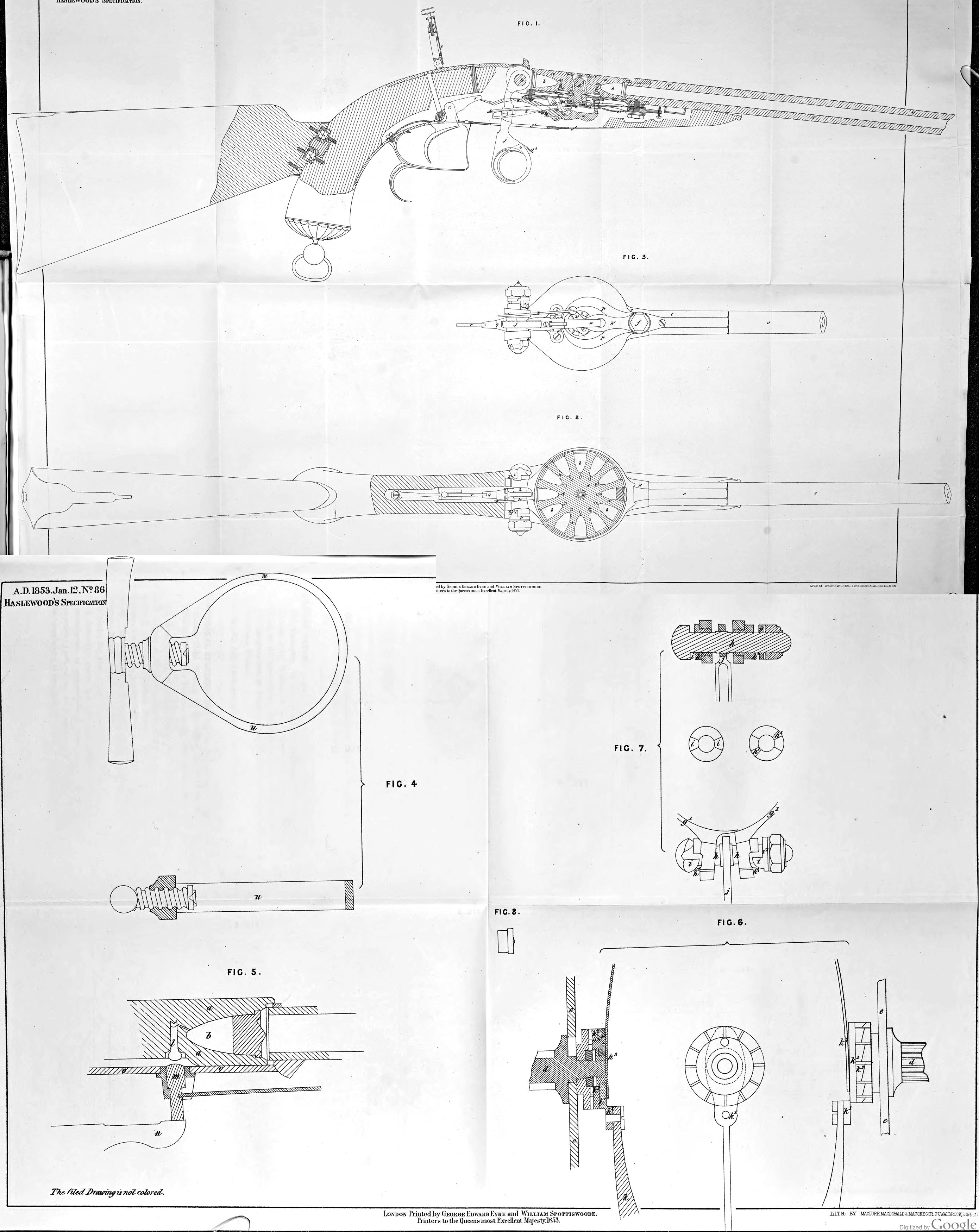
Description of tjie Drawing.
Figure 1, is a longitudinal section. Figure 2, shows an under side view of some of the parts. Figure 3, shews a longitudinal section. Figure 4, shows two views of the ring or hoop for compressing the balF in the charging chambers or breeches. Figure o, shews an enlarged view of a section of one of the charging chambers and part of the lock separately. Figure 6, shews three enlarged views of parts for turning the cylinder with the charging chambers; and Figure 7, shews three views of parts for retaining, for forcing, and retaining the cylinder up to the barrel. In each of these Figures the >ame letters are used to indicate the same parts. Figure 8, shews one of the balls or projectiles with an enlargement or ring.
a, is a cylinder, having several charging chambers or breeches b, b formed in its periphery, and shape of the charging chambers or breeches which is preferred is shewn in the Drawing, r, is the ban-el, the bore of which is somewhat smaller than the outer end of the breech, where the smaller diameter of the ball or projectile enters. The outer end of each breech is formed with two steps or enlargements ; one of them receive the projecting ring of the projectile or ball, that the other receives the end of the barrel e, so that in discharging a ball through the barrel r, the ring or projection or the ball will be held between the end of the barrel c, and the charging chamber, and the other part of the ball will be driven through it. The cylinder a, revolves with an axis d> on which it fits by corresponding teeth; and the axis d, revolves in a slot in the plate e, which is fixed by the screw/, to the screw socket g, in which the end of the barrel screws. The socket ff, has formed with it the loop or ring g\ which encloses the periphery of the barrel a; and the ring