
British 212
LETTERS PATENT to William Tranter, of Birmingham, in the County of Warwick, Gun Maker, for the Invention of “ Certain Improvements in Fire-arms.”
Sealed the 23rd March 1853, and dated the 28th January 1853.
PROVISIONAL SPECIFICATION left by the said William Tranter at the Office of the Commissioners of Patents, with his Petition, on the 28th January 1853.
I, William Tranter, of Birmingham, in the County of Warwick, Gun Maker, do hereby declare the nature of the said Invention for “ Certain Improvements in Fire-arms’’ to be as follows :—
My Invention consists, in the first place, in adapting and applying to pistols and guns a double trigger or two triggers, one portion of the trigger or one of the triggers being used for raising the cock, and the other for discharging the piece* And with this trigger or triggers is combined a safety stop spring to prevent the cock falling, until the catch is withdrawn by means of the discharging trigger, or discharging portion of the double trigger. This double trigger or pair of triggers may be adapted in various forms to different constructions of fire-arms, so as to accomplish in each the double purpose of raising the cock, and at the same time withdrawing the safety stop spring, together with the discharging of the piece. The trigger or triggers may also have various forms of guards adapted and applied to them.
My Invention consists, secondly, in elongating the tube or socket of the revolving chamber in revolving pistols, through which tube or socket passes the short rod or axis on which the chamber revolves. The tube or. socket may be slightly elongated, and the part of the frame into which it is required to fit may be countersunk and prepared to receive it in various ways, so as to increase the facility of applying the revolving chamber to its position in the frame of the pistol, and prevent the liability of the chamber to become inconveniently loose in its position.
My Invention consists, thirdly, in combining the aforesaid double trigger or pair of triggers with the chamber of a gun intended to be loaded at the breech. In this case a strong spring is used, both to hold the chamber in its place and to project the cock upon the nipple. The chamber may be turned round far enough to insert a loaded cartridge by pressing against a projecting lip and collapsing the spring, and the cock may be allowed to strike upon the nipple by withdrawing through the lifting trigger the means by which the projecting force of the spring upon it was counteracted. In this case, too, the parts may be retained on “ half cock.” The cartridge to be used in guns of this description is one so constructed as to dispense with the necessity of removing the closed end before placing it in the chamber by closing the end with a percussion cap.
My Invention consists, fourthly, in combining the double trigger or pair of triggers with the use of a needle or small rod to cause the explosion, in which case the said needle or small rod is projected by means of a spiral or other spring on the withdrawal of a bent lever by the lifting trigger.
And my Invention consists, lastly, in making gun barrels out of two or more spirals of iron or iron and steel wire platted of crossed round a mandril, the wire so platted being afterwards heated to a welding heat, and welded as in the ordinary manufacture of gun barrels, or it may be rolled in such state and with a mandril inside between two flat
SPECIFICATION in pursuance of the conditions of the Letters Patent, ‘ filed by the said William Tranter in the Great Seal Patent Office, on the 28th July 1853.
TO ALL TO WHOM THESE PRESENTS SHALL COME, f,
William Tranter, of Birmingham, in the County of Warwick, Gun Maker, send greeting.
WHEREAS Her most Excellent Majesty Queen Victoria, by Her Letters Patent, bearing date the Twenty-eighth day of January, in the year of our Lord One thousand eight hundred and fifty-three, in the sixteenth year of Her reign, did, for Herself, Her heirs and successors, give and grant unto me, the said William Tranter, Her special license that I, the said William Tranter, my executors, administrators, and assigns, or such others, as I, the said William Tranter, my executors, administrators, and assigns, should at any time agree with, and no others, from time to time and at all times thereafter during the term therein expressed, should and lawfully might make, use, exercise, and vend, within the United Kingdom of Great Britain and Ireland, the Channel Islands, and Isle of Man, an Invention for “ Certain Improvements in Fire-arms,” upon the condition (amongst others) that I, the said William Tranter, by an instrument in writing under my hand and seal, should particularly describe and ascertain the nature of the said Invention, and in what manner the same was to be performed, and cause the same to be filed in the Great Seal Patent Office within six calendar months next and immediately after the date of the said Letters Patent.
NOW KNOW YE, that I, the said William Tranter, do hereby declare the nature of my said Invention, and in what manner the same is to be performed, to be particularly’described and ascertained • in and by the following statement, reference being had to the Drawings hereunto annexed, and to the letters and figures marked thereon (that is to say):
My Invention of “ Certain Improvements in Fire-arms *’ relates, in the first place, to the kind of fire-arms known as revolving pistols or pistols with revolving chambers; and consists, first, in adapting and applying to such fire-arms a double trigger or pair of triggers, combined with a safety stop spring, by means of which the piece is kept from being discharged until the spring is moved out of the way of the cock, which may be done simultaneously with the lifting of the cock and the turning of the chamber by drawing back the lifting trigger or lifting portion of the trigger with the second finger. The discharging trigger may then be moved with facility by the first finger, and the cock projected on the nipple to discharge the piece. This trigger or triggers may be used with various forms of guards. The lifting trigger or lifting portion of the trigger is slotted to hold the discharging trigger or discharging portion of the trigger. My Invention in relation to this kind of fire-arms consists, secondly, in elongating the tube or socket into which the hinder end of the revolving chamber is inserted, in order that the chamber may be thereby screwed forward when required, so as to keep the fore end always tightly fitting in the frame.
My Invention relates, in the second place, to guns intended to be loaded at the breech, and consists in adapting and applying thereto the double trigger or pair of triggers, somewhat modified in form as compared with that above referred to, and in the general arrangement of the parts of the gun, as herein-after more particularly described. In the present instance the trigger is so formed as to be capable of holding the gun at “ half cock ” by means of a tail piece on its end dropping into a notch or recess in the lower part of the cock, by which means the front or discharging part of this double trigger acts as a single trigger. In this case the revolving chamber may be turned round far enough to insert a loaded cartridge by pressing against a lip on the chamber, and collapsing the spring by which it is held in its place. The cartridge to “be used in guns of this description is made so as to have a percussion cap inserted in the end opposite to the ball, by which the necessity for removing its ordinarily closed end may be obviated.
My Invention relates, in the third place, to guns, in which the arrangement and action of the revolving chamber and trigger or triggers are similar to those last referred to, but in which the gun is discharged by means of a needle or small rod projected by means of the spring which holds the chamber in its place, or by means of a spiral spring acting directly upon the rod carrying the needle.
And my Invention refers, lastly, to the mode of manufacturing gun barrels, and consists in making them out of two or more spirals of iron, or iron and steel wire platted or crossed round a mandril, the wire so platted being afterwards heated to a welding heat, and welded as iij the ordinary manufacture of gun barrels.
In order, however, that my Invention may be fully understood I will proceed to describe it more particularly by the aid of the accompanying Drawings, in which are contained representations of the parts above referred to.
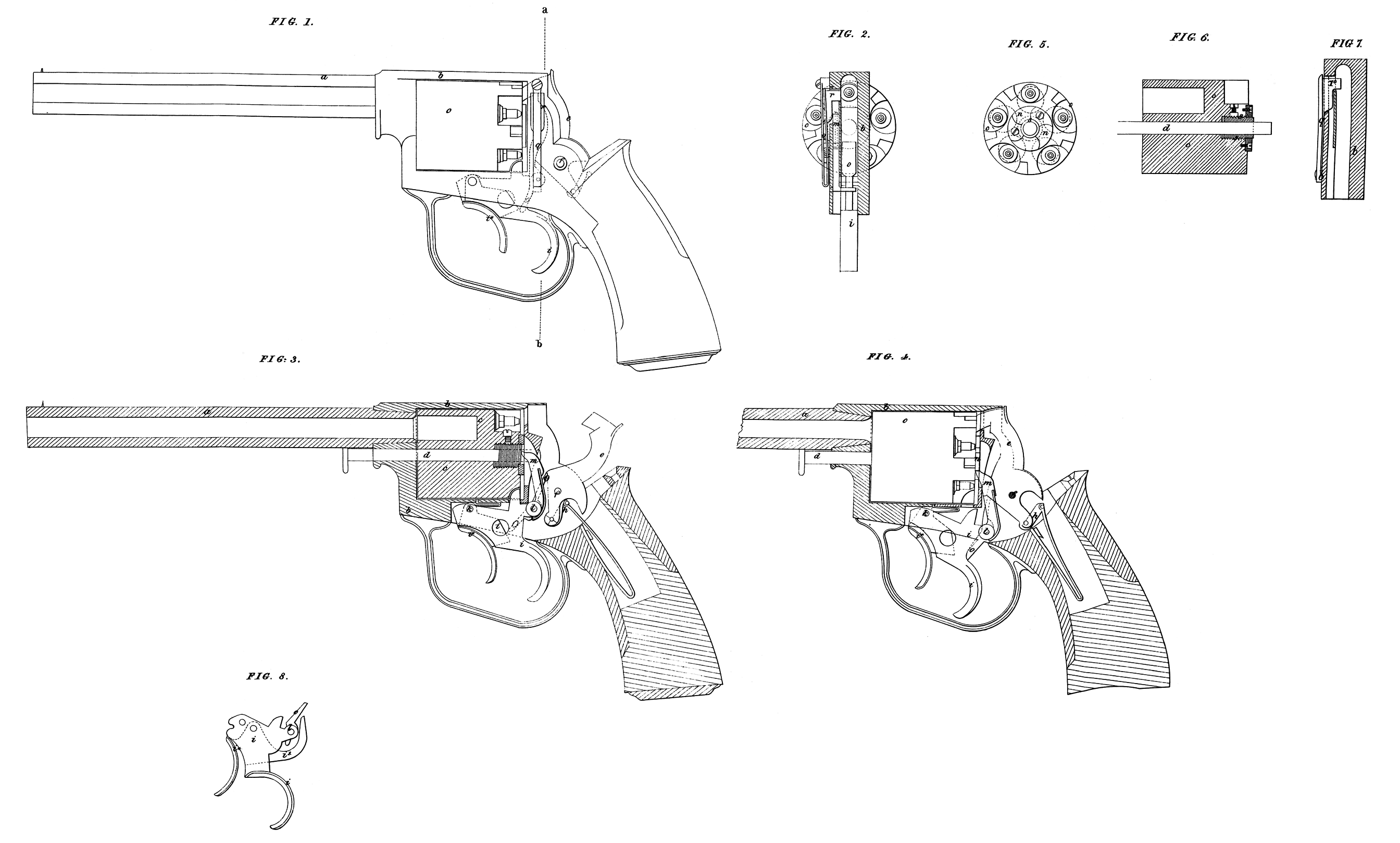
Figures 1, to 8, Sheet I., relate to revolving pistols. Fig. 1, is a side view of a pistol with my improved trigger or triggers and safety stop spring applied thereto, and shewing the cock projected on to the nipple, and the trigger or triggers drawn back. Fig. 2, is a transverse section of the same in the line a, b, of Fig. 1. Figures 3, and 4, are longitudinal sections, shewing the parts in different positions. Fig. 3, shewing the cock raised, and the lifting trigger drawn back; and Fig. 4, shewing the cock projected on to the nipple, having been liberated by means of the discharging trigger: Fig. 5, is an end view of the revolving chamber, with the nipples upon it. Fig. 6, is a longitudinal section of the same, shewing its elongated socket. Fig. 7, is a transverse vertical section of the frame within which the chamber turns, shewing the safety stop spring; and Fig. 8, represents another form of lifting and discharging trigger. In these several Figures the same letters of reference indicate corresponding parts, a, is the barrel of the pistol; by the ordinary solid frame within which the revolving chamber Cy is placed, so as to “be capable of turning the required distance on the pivot or axle d, inserted in the frame 6, in the usual manner; e, is the cock turning on a centre /, and projected on to the nipple by riieans of the spring g, and tail piece h. The lifting trigger is shewn at z, and the discharging trigger at i*. These triggers turn on a centre Jc. The trigger i, is slotted to hold the trigger i*. On the pivot or centre Z, is fixed the spring pall in, which causes the chamber to revolve the required distance by acting against a tooth in the ratchet w, on the end of the chamber c, in the usual manner. On this pivot or centre Z, is also fixed a tail piece or lever o, the upper end of which serves to raise the cock by pressing against a small recess in the same, as shewn at Figures 3, and 4, the lower end being acted on by the discharging trigger i*, in order to withdraw the upper end from the said recess. The trigger i, is brought back to the position shewn in Fig. 4, after the discharge of the pistol by the pressure of the spring p. The safety stop spring is shewn at on the inner side of which is attached a projecting piece r, which projects inwards a sufficient distance (as shewn at Fig. 7,) to prevent the cock from going forward to the nipple until it is moved outwards into the position shewn in Fig. 2, by the pall or tail piece m, on the lifting trigger pressing against the curved end of the projecting piece r.
The action of this pistol is as follows :—The parts may be brought into the position shew at Fig. 3, by drawing back the trigger by the second finger. The effect of which will be to raise the cock by means of the tail piece or lifter o, also to turn the chamber c, the required distance by means of the pall m, and also to remove the safety stop spring q, out of the position shewn at Fig. 7, into that shewn at Fig. 2, so that it may no longer present an obstacle to the projection of the cock on to the nipple. The pistol may then be discharged by a slight pressure of the first or forefinger against the trigger i*, the end of which will thus be made to act upon the lower end of the tail piece o, arid withdraw its upper end from the recess in the cock as shewn by dotted lines in Fig. 1. The removal of the pressure of the fingers from the trigger or triggers will ’cause the parts to assume -the position shewn atFig, 4, ready for another discharge.
It will be seen that at Fig. 8, the trigger or triggers are somewhat different in form from that just described, also that the tail piece or lifter 0, is acted upon at the upper instead of the lower part. The action is otherwise the same as that above described, and I would here remark that my Invention is not confined to the exact forms thus represented, provided the action be in its general features the same as that above described.
I will now describe the elongated socket for the chamber c, which is represented at s, in Figures 3, and 6. It has a screw formed on it as shewn, and is prevented from turning by means of a set screw or pin f, inserted at the hollow part of the chamber c, (see Fig. 6.) This screwed socket may also be formed with a flange upon it, and may be used to hold the ratchet n, in the end of this chamber c, without screws; or the ratchet n, may be put on the flange of the socket s, and serve as a lock nut to prevent the socket from moving. The socket s, may also be made without a screw formed upon it, and in such case metallic washers may be used instead. When the ratchet ny is used to keep the socket s, in its place, screws must be used with the ratchet. The frame b9 may be countersunk in order to receive the end of the socket s. By means of this elongated socket s9 it will be seen that the chamber c, may be screwed forward or tightened against the fore part of the frame b, should it be required.
I proceed now to describe the second part of my Invention, which relates to guns intended to be loaded at the breech. Fig. 9, is a side view of such gun. Fig. 10, is a transverse section in the line c, d, of Fig. 9, looking towards the stock of the gun. Fig. 11, is a similar section in the line e, /, of the same Figure, looking towards the barrel. Fig. 12, is a longitudinal section, shewing the positions of the parts at the time when the cock is projected on to the nipple. A, is the loading chamber, which is kept in its position in the frame B, by means of a double acting spring C, pressing against the projection A* and it is made to fit tightly against the end of the barrel by means of the holt and screw D, and E. The chamber A, has on one side of it a lip F, by pressing upon which the chamber may be turned down to receive the charge; the spring C, also projects the cock. By means of this spring likewise the pivot or axle G, of the chamber C, is kept in its position; the end of the said spring, by bearing on one end of the arm or leaver H, causes a pin or stud on the same to pass into a hole in the axle G, and thereby hold it. I, is the lifting trigger, and I* the discharging trigger, which are shewn in different positions in Figures 12, and 14; the former Figure shewing the trigger or triggers before they are drawn back, and the latter shewing the same with the parts as they would appear when the cock is lifted and ready to be projected on to the nipple.
The action of this gun is as follows;—The trigger I, is drawn back into the position shewn by dotted lines in Fig. 12, by which means the tail piece L, is made to move fonvard the bent arm or lever M, connected with the double spring C. In this manner the cock is lifted, and it is liberated by pressing back the trigger I*, which is thereby withdrawn from the notch in the bent arm or lever M, turning on a common centre with the cock, and the cock is projected on to the nipple by the tension of the spring C. It will be seen that in this case the lifting trigger only lifts the cock, which may be done by the hand without such trigger, so that, if preferred, a single trigger, as at I*, may be employed alone for this kind of gun. I would also remark, that the general arrangement of the parts of the gun just described may be adapted and applied to guns and pistols with revolving chambers. In the cartridge to be used with this gun the ball is elongated, with a shoulder extending into the body of the cartridge. At the reverse end the percussion cap is inserted in such a manner as to obviate the necessity for breaking off the end before use. Fig. 15, represents in longitudinal section the same kind of gun, but in which the explosion is to be produced by forcing a needle or small rod into the cartridge. It will be seen that the double acting spring C, which holds the chamber A, in its place is connected so as to act upon the rod to which the needle N, is attached by means of the bent arm or lever M, Which in this case is lengthened upwards in order to adapt it for the purpose. In other respects the action of the gun is the same as that above described.
With reference to my improvements in the manufacture of gun barrels, above referred to, I would here remark, that the wire, when platted, is to be heated to a welding heat, and welded in the usual manner. The wire may be circular or of other form in the cross section.
Having thus described the nature of my Invention, and in what manner the same is to be performed, I would have it understood that I do not mean or intend to confine myself to the precise forms and arrangements of the parts shewn and described, as the same may be varied in some particulars without departing from the general features of my Invention. I would also here remark, that although I have described the double trigger or pair of triggers as applied to certain forms and constructions of fire-arms, yet my Invention is not confined thereto. And I would further remark, that the gun described under the second head of my Invention may be combined with the double trigger or pair of triggers as represented and described, or it may be combined with a trigger of another form.
I do not, however, claim as of my Invention the several well known parts of fire-arms which have been necessarily represented and referred to ill order to make the object and essential character of my Invention evident. But what I claim as of my Invention is,—
First, the lifting and discharging trigger or triggers, combined with the safety stop spring, and capable of being acted upon in the manner and with the effect described.
Secondly, the mode described by which the revolving chamber may be made to fit with the required tightness in the frame which carries it.
Thirdly, the modified form of trigger or triggers applied to guns to be loaded at the breech, and the general arrangement and construction of such guns as described.
Fourthly, the same applied to guns to be fired by means of a needle.
Fifthly, the use of a cartridge of the kind described.
And lastly, the manufacture of gun barrels out of spirals of iron, or iron and steel wire, platted or crossed round a mandril as described. In witness whereof, I, the said William Tranter, have hereunto set my hand and seal, this Twenty-sixth day of July, in the year of our Lord One thousand eight hundred and fifty-three.
WILLIAM TRANTER, (l.s.)
Witnessed by William Spence/
Patent Agent.