
US 28331
UNITED STATES PATENT OFFICE.
EDW. SAVAGE, OF CROMWELL, AND H. S. NORTH, OF MIDDLETOWN, ASSIGNORS TO SAVAGE REVOLVING FIRE ARMS COMPANY, OF MIDDLETOWN, CONNECTICUT.
IMPROVEMENT IN REVOLVING FIRE-ARMS.
Specification forming part of Letters Patent No. 28,331, dated May 15, 1860.
To all whom it may concern:
Be it known that we, Edward Savage, of Cromwell, in the county of Middlesex and State of Connecticut, and Henry Savage North, of Middletown, in the county of Middlesex and State of Connecticut, have invented certain new and useful Improvements in Revolving Fire-Arms; and we do hereby declare that the following is a full, clear, and exact description of the same, reference being had to the accompanying drawings, forming part of this specification, in which—
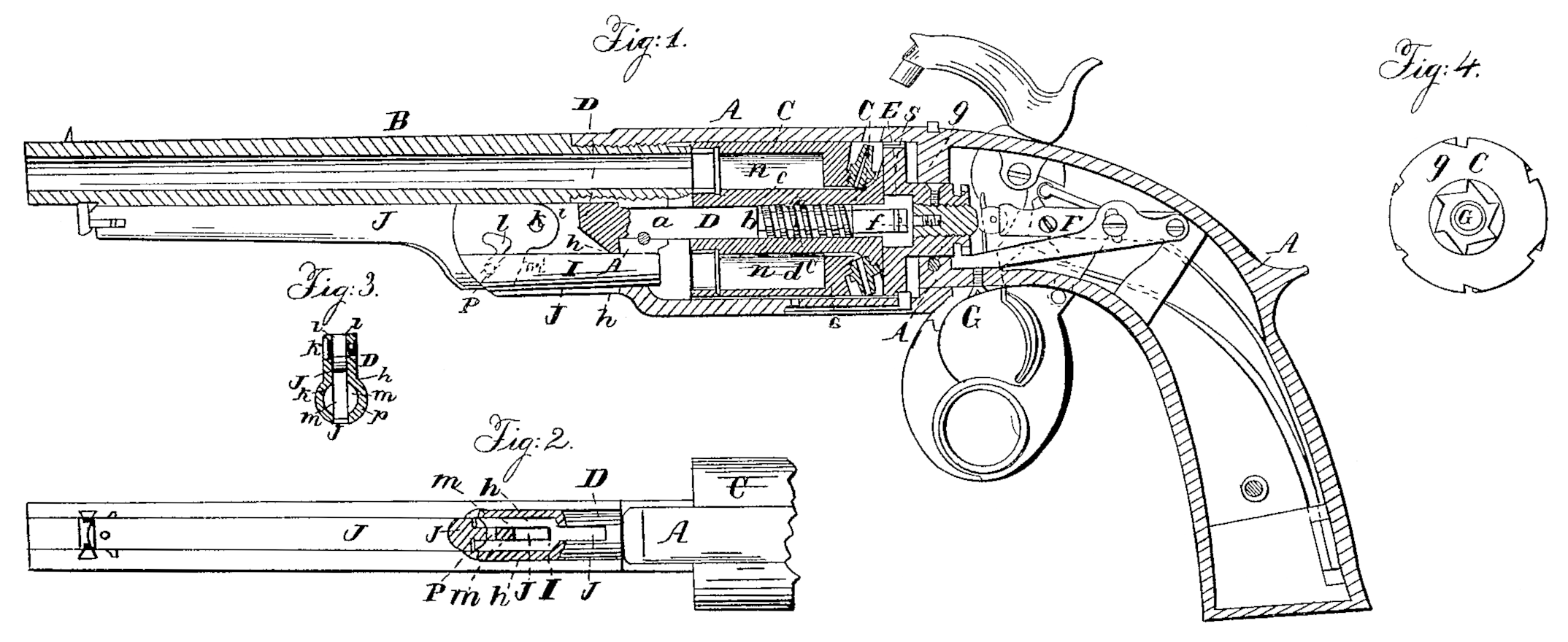
Figure 1 is a central longitudinal section of a revolving pistol with our improvements. Fig. 2 is an under side view of the barrel and rammer, exhibiting the latter partly in section. Fig. 3 is a transverse section of the rammer. Fig. 4 is a back view of the many-chambered cylinder,
Similar letters of reference indicate corresponding parts in the several figures.
Our invention consists in a novel construction of the stationary pin on which the many-chambered cylinder rotates and a novel mode of applying a spring, in combination with such pin and the many-chambered cylinder, for the purpose of forcing back the said cylinder from contact with the rear of the barrel preparatory to its rotary motion on the said pin.
It also consists in the employment, in combination with the regulating-screw, which constitutes part of the subject-matter of Letters Patent of the United States, dated June 17, 1856, granted to Henry S. North, of a thimble or bushing applied to the rotary recoil-shield, as hereinafter described, and serving the two purposes of a bearing for the rear end of the stationary pin on which the cylinder rotates and a bearing for the head of a set-screw, which serves the purpose of securing the said regulating-screw.
It also consists in the mode of applying the aforesaid set-screw, in combination with the said thimble or bushing and the regulating screw, as hereinafter specified; and it further consists in an improved mode of operating the rammer.
To enable those skilled in the art to make and use our invention, we will proceed to describe its construction and operation.
A is the metal frame, which contains the rotating many-chambered cylinder C, the recoil-shield S, and the lock, and constitutes the principal portion of the stock, and into which is secured the barrel B.
ID is the stationary pin upon which the cylinder C rotates, which may be termed the “cylinder axis-pin,” fitting tightly into a hole provided for it in the front part of the frame A, and into the central thimble or bushing, E, of the recoil-shield S, which will be presently described, and secured in its place by means of a transverse pin or screw, a, which passes transversely through the frame A. This cylinder axis pin is made of uniform size for about half its length, commencing at its head D’, and the other portion smaller, but of uniform size, so as to form a shoulder, b, which occupies a position some distance within the cylinder when in its place, as shown in Fig. 1. The cylinder is bored centrally from its front end nearly all the way through of the full size of the larger portion of the pin D; but at the rear its bore is diminished to the size of the smaller portion of the said pin, so as to form a shoulder, c; or a similar shoulder may be formed by boring the cylinder throughout of the larger size and inserting a tight bushing at its rear end to fit the smaller portion of the pin. By constructing the cylinder and pin each with a shoulder, as described, an annular cavity, e e, is formed between them for the reception of a coiled spring, d, which encircles the smaller portion of the pin, and which, acting against the shoulder b of the pin as a base, presses constantly against the shoulder c in the cylinder, and so forces back the latter away from the barrel, when it is permitted to do so by the toggle F or other contrivance that is employed for driving up the cylinder toward the barrel before firing, and holding it in close contact there with during the discharge.
The thimble E (see Fig. 1) is driven or other wise inserted very tightly into a central cavity provided to receive it in the front of the recoil shield. In the construction of the recoil-shield it is more convenient to have the female screw-thread which receives the regulating-screw G extend right through it, that the recoil-shield may be placed on a screwed mandrel or arbor, to be thereon turned in a lathe; and after the shield has been turned in this way we remove it from the mandrel or arbor and place it in a chuck, and then turn out or counterbore the cavity for the steel thimble or bushing E, which must have an external diameter considerably larger than the regulating-screw G. The said, thimble or bushing is bored centrally to receive the rear end of the cylinder axis-pin D, to which it constitutes a bearing, and the bore is continued to a greater depth than the said pin projects into it to make room for the head of the set-screw f, which passes through a smaller hole back of such bore…and screws into a tapped hole in the center of the regulating-screw. By screwing up the set-screw f so that its head bears firmly against the back of the bore in the thimble or bushing the regulating-screw G is held very tightly and prevented working out of its place by the repeated firing of the piece. It is scarcely necessary to state that before any adjustment of the regulating screw is made the screw if must be unscrewed a little way. We have represented in Fig. 1 another set-screw, g, screwed through a tapped hole in the journal of the recoil-shield and bearing upon the screw; but this is found in practice to be much less reliable than the set screw f, when both are used separately, and is perhaps unnecessary when the screw f is used.
The rammer is attached to the head D’ of the cylinder axis-pin, which head is formed with a cylindrical cavity, h, running entirely through it parallel with the axis of the pin itself and with the chambers n n of the cylinder, and which has a longitudinal slot, i, above and a similar slot, j, below the said cavity, said ‘slots ranging exactly with each other and extending from the extremity of the head nearly the whole length of it. The plunger I of the rammer is fitted to slide in the cylindrical cavity h, and the lever j, by which the said plunger is worked, is made with a slotted cam-like head, which fits into the slots i j of the head D’ and into a corresponding slot, m, in the plunger, and which is attached to the said head D’ by a fulcrum-pin, k, passing through the upper slot, i. The cam-like slot l of the said lever receives a pin, which is inserted through the slot m of the plunger, and which is fixed relatively to the plunger. The said slot l is of such form that by pulling down the lever from the position close to the barrel and in line with the pin D (represented in Fig. 1) it is caused by its action on the pin p to force the plunger back in the cavity h of the head D’, which constitutes a guide to guide it into the chambers as they are successively brought opposite to the said cavity by turning the cylinder. The slot, being of such form eccentric to the fulcrum k as to produce the above operation, will of course be caused to operate upon the said pin p to draw forward the plunger from the chambers and out of the way of the cylinder by the return of the lever J to the position close to the barrel. (Represented in Fig. 1.)
The above operation of the plunger, it will be understood, is effected within the head of the cylinder axis-pin.
What we claim as our invention, and desire to secure by Letters Patent, is—
1. Placing the coiled spring which forces back the rotating cylinder away from the muzzles of the charge-chamber and covering it with the shoulder.b of the cylinder axis-pin, so that its action cannot be clogged by the ac: cumulation of smoke, burned powder, or dust from the muzzles when fired, and also increasing the facility with which the rammer can be put in and taken out, all as herein shown and described.
2. The employment, in combination with the regulating-screw, G, of a thimble or bushing, E, applied to the recoil-shield, to serve at the same time as a bearing for the rear end of the cylinder axis-pin D, and a bearing for a set-screw, f, by which to secure the regulating screw, substantially as herein described.
3. The set-screw if, applied in combination with the thimble or bushing E of the recoil shield and with the regulating-screw G, substantially as and for the purpose herein described.
4. The combination, with the plunger I, fitted to a guide in the head of the cylinder axis-pin D, as described, of the lever J, fitted to the slots i and j of the said head and to a slot, m, in the plunger, and connected to the said head by a fulcrum-pin, k, and with the plunger by a cam-like slot, l, and pin, p, substantially as herein specified.
EDW. SAVAGE.
HENRY S. NORTH.
Witnesses:
Clark Elliott,
Jonathan Barnes.