
US 28460
UNITED STATES PATENT OFFICE.
WILLIAM H. ELLIOT, OF PLATTSBURG, NEW YORK.
IMPROVEMENT IN REVOLVING FIRE-ARMS.
Specification forming part of Letters Patent No. 28,460, dated May 29, 1860.
To all whom it may concern:
Beit known that I, Wm. H. Elliot, of Plattsburg, in the county of Clinton, in the State of New York, have invented a new and Improved Repeating Pistol with Stationary Barrels; and I do hereby declare that the following is a full and exact description thereof, reference being had to the accompanying drawings, and to the letters of reference marked thereon.
Similar letters of reference indicate the same devices in all the figures.
To enable others skilled in the arts to comprehend, make, and use my invention, I will proceed to describe its nature, construction, and operation.
The nature of my invention consists in a novel method of employing, combining, or arranging certain devices for firing a series of stationary barrels, by which great compactness, convenience, and durability are secured.
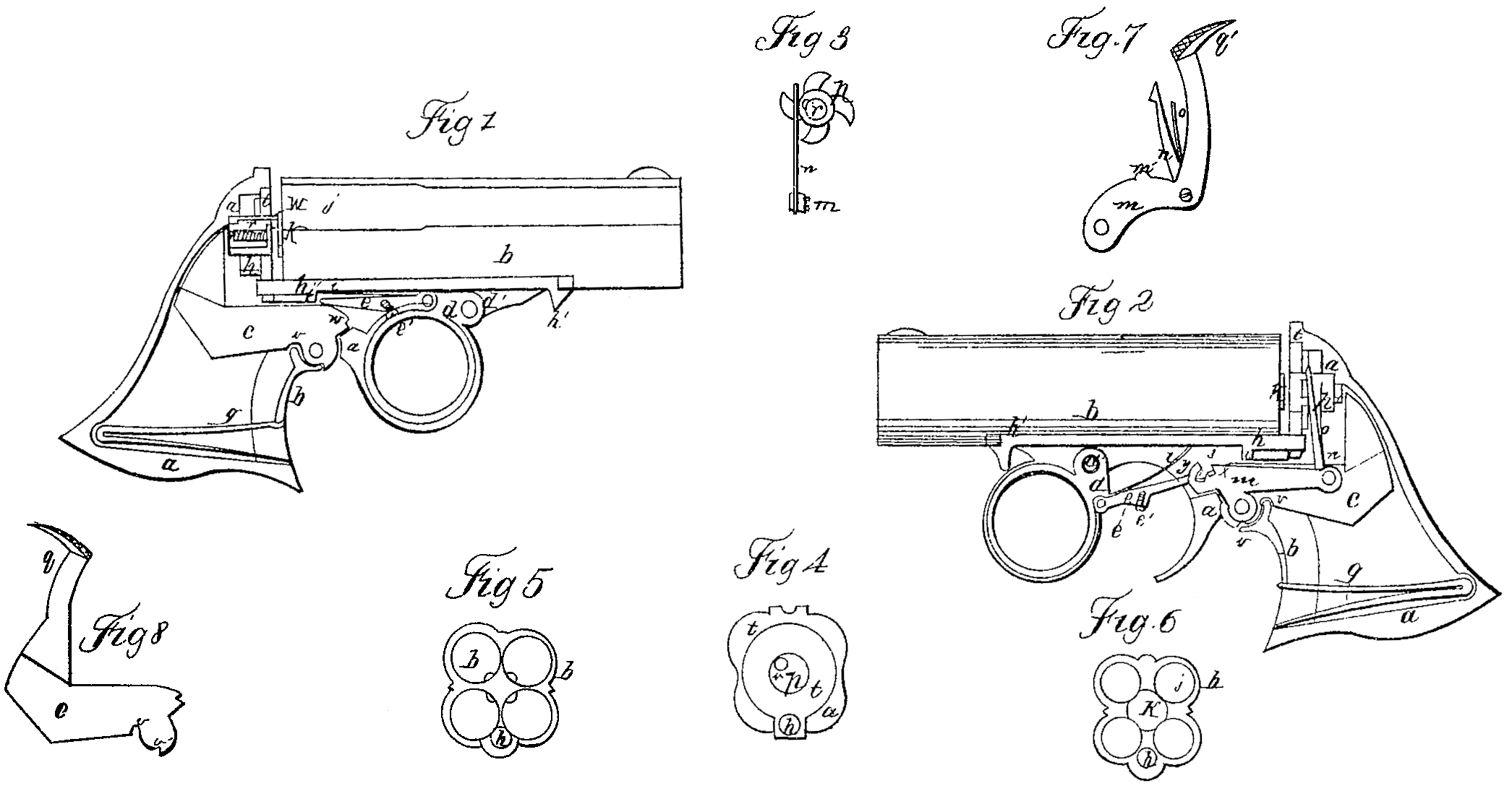
Figure 1 is a perpendicular section of a pistol, showing the lock. Fig.2 is the same, showing the revolving devices in elevation. Fig. 3 is an elevation of the revolving disk with its firing-pin and revolving pawl. Fig. 4 is an elevation of a breech-plate. Fig. 5 is an elevation of the end of the barrels, showing the cartridge in the chambers, and also the effects of the exploding-point upon them. Fig. 6 is an elevation of the end of the barrels, showing the projection or anvil. Fig. 7 is an elevation of a revolving lever so constructed as to operate upon the hammer to raise it, and upon the disk to revolve it. Fig. 8 is an elevation of a hammer so constructed as to be operated by the thumb or by the trigger.
a is the frame; b, barrels; c, hammer; d, trigger; d’, pivot of barrels and trigger; e, cocking-pawl; e’, set-screw of the same; f, stirrup; g, mainspring; h, bolt for holding the barrels in place; h,’ thumb-piece of the same; i, spring of pawl e, i’, projection on lower side of bolt h; j, chambers; k, anvil; C, cartridge; m, revolving lever; m’, projections on same over the hammer; n, revolving pawl; o, spring of the same; p, revolving disk; q, thumb-piece on hammer; q’, thumb-piece on revolving and cocking lever; , firing-pin; s, spring of the same; t, breech-plate; u, exploding-point of the for the purpose of firing the firing-pin; v, main seat of the stirrup in the hammer; v’, stop-seat; w, notch by which pawl e operates the hammer; ac and y, notches on lever m, by which pawl e operates the revolving devices; z, pin on the side of pawl e.
This pistol is loaded by withdrawing the bolt h from the breech-plate t by means of thumb piece h’, when the rear end of the barrels may be raised, turning upon pivot d’ sufficiently to pass the cartridges into the chambers over the breech-plate. The barrels may then be returned to their place and the bolt pushed back into the breech-plate. To withdraw the bolt it is necessary to push the trigger about halfway forward first, otherwise the spring i will strike against projection i’ and prevent the bolt from being withdrawn. These devices are so arranged to prevent the barrels from becoming unbolted in the pocket. If, by accident, the trigger should get pushed forward and the barrels unbolted, the spring i and pawl e will push the bolt back into its place again in the act of firing.
To fire this pistol the trigger must be moved forward to the position represented in Fig. 2, when the rear end of pawl e falls into notch w on the hammer, and as the trigger is carried backward again the hammer is raised until the side of the trigger comes in contact with the screw e’, by which means the rear end of pawl e is elevated, when the hammer falls upon the firing-pin, as represented in Fig.1, which drive the firing-pin forward against one of the cartridges and fires it.
The stirrup f has two seats in the hammer, and when it is home in both seats the hammer stands raised a short distance from the firing-pin, and the pin is also thrown back from the cartridge by its springs, the purpose of which is to relieve the cartridge from the pressure of the exploding-point u, so that the relative position of these devices may be changed without obstruction from said pressure for the purpose of firing the next cartridge. After the hammer has expended its force upon the cartridge it is caused by the pressure of the stirrup upon the seat v’ to return to the position represented in Fig. 2. While the trigger is drawn backward the rear end of lever m is depressed; but as the trigger is pushed forward for the purpose of firing the pin z in the side of pawl e catches notchy, carrying it forward and raising the rear end of lever m, as seen in Fig. 2. As the trigger is carried back again the same pin strikes notch x, carrying it backward and depressing lever m, which draws down pawl n, thus causing the disk p to revolve one-fourth of a revolution, bringing the point u over the next cartridge.
The projection k on the rear end of the barrel serves as an anvil between which and the point u the rim of the cartridge is crushed. This projection is a slight elongation of the barrel or chamber arranged on the side upon which the exploding-point strikes and directly under said point, the purpose of which is to provide for any irregularity in the construction of the cartridge, so that the rim of the cartridge may always find a firm resting-place at the side of the chamber under the exploding point.
A hammer arranged in the ordinary way in combination with any practical device for distributing its force among several stationary charges in regular order tends greatly to compact a pistol, as it requires less room in the frame for barrels that do not revolve than for those that do, and also as stationary barrels require no center-pin, and consequently need not be separated to make room for one; but when such a device for distributing the force of the hammer is employed in combination with a hammer so arranged in relation to the frame or handle of the pistol that its face swings downward within the handle in front of the hand, while its pivoted end is connected to the pistol at some point forward of the free end, a greater degree of compactness is obtained than could be had without this peculiar combination. A similar result is also produced by employing a hammer arranged as above specified in relation to the frame with chambers left open at their rear end and with a breech-plate; but when these three conditions— viz., the hammer arranged as above stated, the peculiar construction of chambers with their breech-plate, and the distributing device— are employed together a still greater degree of compactness is obtained. By so arranging the firing-pin that it projects from the rear side of the disk p at the center the gliding blow of the hammer has no tendency to revolve it, as it would if the firing-pin passed directly through the disk at distance from the center.
The several barrels are arranged around a common center. In this center is the axis of the disk, and parallel with the axis of the disk, or nearly so, is the motion of the firing-pin. This peculiar arrangement of these devices is necessary to communicate the force of the hammer to a series of barrels arranged around a common center.
To fire a cartridge of the character of those employed in this invention— viz., the Smith & Wesson cartridge— it is necessary that the exploding-point be small compared with the size of the head of the cartridge, and that said point be made to penetrate a little distance into its metal shell. Now when the hammer must necessarily be arranged, as shown in the drawings, so as to strike a gliding blow upon the cartridge, coming down upon it with considerable lateral motion, all the resistance that is offered by the shell of the cartridge to the lateral motion of the hammer only goes to lessen the effect of the blow. A hammer falling in such a manner upon a percussion-cap glides over the cap without penetrating it, and consequently little or none of its force is lost by its lateral motion. To obviate this difficulty of penetrating the cartridge by an exploding-point having a lateral motion it is necessary that this point be employed independent of the hammer, and so arranged in connection with it and with the cartridge that while it receives upon its hardened and polished head a gliding blow from the face of a hammer possessing the same qualities it shall penetrate the cartridge perpendicular to the surface of the shell, as shown in the drawings. This little device introduced between the hammer and cartridge in the above connection lessens nearly one-half of the necessary force of the mainspring, which is a matter of great importance to pocket-pistols.
Chambers that are bored entirely through and left open for the purpose of being charged in the rear, as shown at j, are much more safely employed with a breech-plate attached to or supported by the frame, as no hammer can be made strong enough to resist the recoil of the cartridge without danger of accidents.
I make no claim to the peculiar arrangement of the hammer herein specified in relation to the frame, when employed with chambers closed at their rear end by a breech-pin or otherwise. Nor do I claim in this application said arrangement of the hammer in relation to the frame, when employed with chambers bored entirely through for the purpose of being charged in the rear, when these devices are not employed with a breech-plate. Nor do I claim the employment of a movable exploding-point for distributing the force of the hammer among the charges, when said point is attached to and swings back and forth with the hammer.
Having described my invention, what I claim, and wish to have secured to me by Letters Patent, is—
1. The employment of a hammer, arranged as specified in relation to the frame, in combination with chambers bored entirely through and left open at their rear end, and with a breech-plate, as and for the purpose specified.
2. The employment of a movable exploding-point for distributing the force of the hammer among the charges, so as to fire them in a certain order, when said point is employed with but detached from a hammer arranged as specified in relation to the frame.
3. The arrangement of the head of the firing pin r in the central line or axis of the disk p, so that a gliding blow from the face of the hammer upon the head of the firing-pin shall have no tendency to revolve the disk, as specified.
4. The employment between the chamber j and the hammer c of a firing-pin, or its equivalent, when said pin is so arranged and employed with the hammer that while it receives a gliding blow from the face of the hammer it penetrates the cartridge in a direction perpendicular, or nearly so, to the surface of the shell, as and for the purpose specified.
5. The employment of stop-seat v’, in combination with main seat v, when these devices are employed with an exploding-point which penetrates the surface of the cartridge, as specified.
6. The employment of disk p, firing-pin r, in combination with a series of stationary barrels arranged around a common center, when these devices are so arranged that the longitudinal motion of the firing-pin within the disk shall be parallel with the axis of the disk and with E. bores of the barrels, or nearly so, as set forth.
WM. H. ELLIOT.
Witnesses:
F. C. Shepard,
James Mathews.