
Britain 997
A.D. 1866, 7th APRIL. N° 997.
LETTERS PATENT to Edward Thomas Hughes, of the Firm of Hughes and Son, Patent Agents, 123, Chancery Lane, London, for the Invention of “Improvements in Revolving Fire-arms”—A communication from abroad by James Benjamin Doolittle and George Otis Downing, of New Haven, State of Connecticut, United States of America.
Sealed the 3rd October 1866, and dated the 7th April 1866,
PROVISIONAL SPECIFICATION left by the said Edward Thomas Hughes at the Office of the Commissioners of Patents, with his Petition, on the 7th April 1866.
I, EDWARD THOMAS HUGHES, of the Firm of Hughes and Son, Patent Agents, In, Chancery Lane, London, do hereby declare the nature of the said Invention for “Improvements in Revolving Fire-arms,”— a communication to me from abroad by James Benjamin Doolittle and George Otis Downing, of New Haven, State of Connecticut, United States of America, to be as follows:—
This Invention relates to improvements in that class of fire-arms which receive several metallic cartridges into a revolving cylinder which is caused to revolve by the act of cocking, so as to present successively each of the cartridges to the barrel for discharge, and the Invention consists chiefly in the peculiar construction of the cylinder and the mechanism combined therewith, for operating the arm.
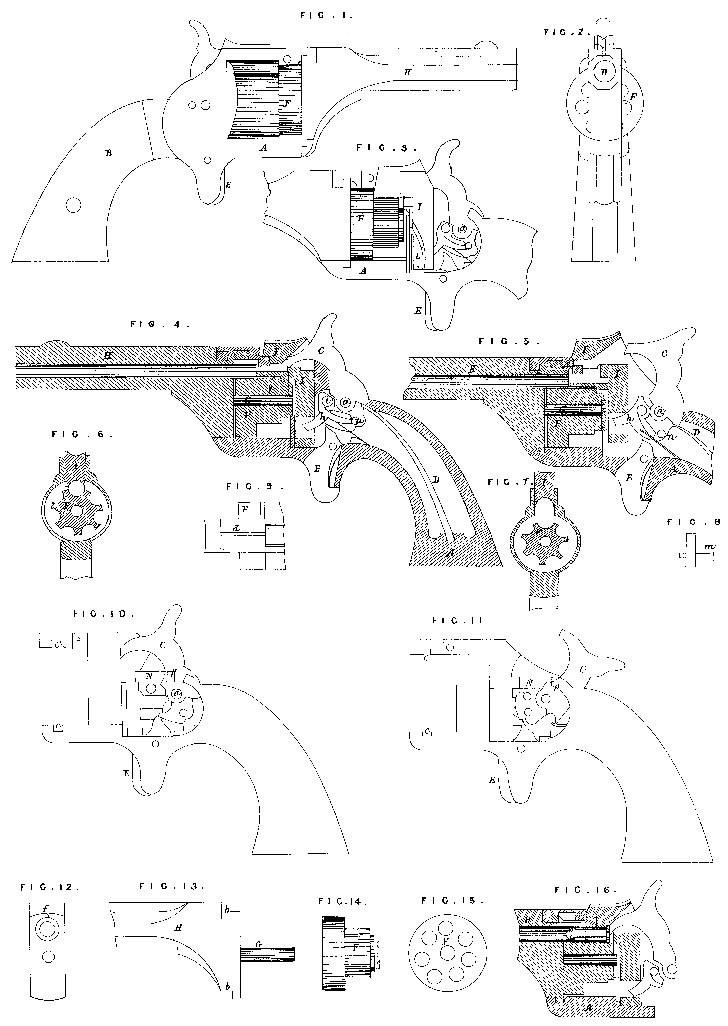
To enable others to carry out this Invention I will proceed to fully describe the same as illustrated in the accompanying Drawings, which represent in no. 1 a side view; Fig. 2, a front or muzzle end view; Fig. 3, a side view with the side plate removed; Fig. 4, a longitudinal section; and Figs. 5 to 16 inclusive illustrate the operation of the Invention.
A is the frame, within which are placed the operative parts, and enclosed by a stock B in the usual manner; C is the hammer, pivoted at a; D, the main spring; and E, the trigger, all constructed and operated in a common and well-known manner. F, the cylinder, differs from the cylinder as commonly constructed in that instead of having the chambers entirely through the cylinder the rear part of this cylinder, as seen in Fig. 14, is cut away, retaining only so much of the entire cylinder as will enclose the ball and just extend over the front end of the cartridge shell, the front of the cylinder presenting the usual appearance, as seen in Fig. 15, the rear being cut down to the centre of the chamber, as seen in Fig. 6. The said cylinder is placed in the frame in the usual position, and secured thereto by a pin G fixed to or made a part of the barrel H, the said barrel being provided with projections b above and below, as seen in Fig. 13, which lock into corresponding notches, s, Fig. 10, the said pin G passing centrally through the cylinder, and when the barrel is thus placed in the frame in the proper position a latch d, see Figs. 9 sad 16, catches into a notch f, see Fig. 12, to hold it in its proper position. I is a yoke arranged to slide vertically within the frame at the back of the cylinder, and extending over the cylinder so as to set down upon the cylinder and complete the chamber, which is in line with the barrel, as seen in Figs. 6 and 16. The said yoke is moved up and down by the operations of a lever h having its fulcrum at i, and acted upon by a pin n on the hammer, as seen m Figs. 4 and 5. As represented in Figs. 4 and 6, the yoke is down, forming a complete chamber; and to raise the yoke I draw the hammer back, as see, in Fig. 5, and the pin it bearing against the lever h, which extends kite the lattice in the lower end of the yoke I, will torn the lever and raise the yoke, as seen in Fig. 5, and when sufficiently raised for the purpose hereafter shown the pin it passes over the end of the lever h, and drops off at the back of a projection m, see Fig. 8, and permits the yoke and lover h to return to the position seen in Figs. 4 and 6. To the said yoke I is attached a pawl L which acts upon a ratchet on the rear of the cylinder to revolve the cylinder at. each upward movement of the yoke. When the yoke is down, to complete the chamber in Figs. 4 and 6, it is necessary to lock it in that position before the discharge takes place, and for this purpose I place a slide N in the frame, as seen in Fig. 10, which is operated by a pin P on the hammer, so that when the hammer is drawn back, as from the position in Fig. 10 to that in Fig. 11, the slide also is drawn back, and when the hammer is returned the slide N will be forced forward, and enter a notch in the yoke, and securely hold the yoke down upon the cylinder. To charge the arm, remove the barrel, turning it from the notches in the frame which secures it thereto, take the cylinder from the frame, insert the cartridges in the usual manner, return the cylinder and barrel to their respective places, and the arm is charged preparatory to firing; then draw the hammer to full cock, and release it in the usual manner. The hammer passes through a mortice in the yoke, striking the cartridge to discharge it in the usual manner. Then for a second dis-charge again draw back the hammer, and in this operation the yoke I will be raised to permit the discharged shell to pass on and a new cartridge to be presented to the barrel, and the cylinder will be revolved, and thus present the new cartridge. When thus presented the yoke I will drop down on to the cartridge, thus forming a chamber around the cartridge, and in the return of the hammer the yoke will be locked in the manner described and the second cartridge discharged, and so on until all the cartridges have been discharged; then remove the cylinder, eject the discharged shell from the cylinder (the pin G on the barrel being used for that purpose), place other cartridges in the cylinder, and operate as before. The latch d which holds the barrel in its position extends at its rear end downwards so as to rest upon the cartridge within the chamber, so that while a cartridge is in line with the barrel the barrel cannot be turned from its position, and will he thus held until the cylinder has made a partial movement so as to permit the latch to be raised from the notch in the barrel.
SPECIFICATION in pursuance of the conditions of the Letters Patent, filed by the said Edward Thomas Hughes in the Great Seal Patent Office on the 6th October 1866.
TO ALL TO WHOM THESE PRESENTS SHALL COME, I, EDWARD THOMAS HUGES; of the Firm of Hughes and Son, Patent Agents, 123, Chancery Lone, London, send greeting.
WHEREAS Her most Excellent Majesty Queen Victoria, by Her Letters Patent, bearing date the Seventh day of April, in the year of our Lord One thousand eight hundred and sixty-six, in the twenty-ninth year of her reign, did, for Herself, her heirs and successors, give and grant unto me, the said Eduard Thomas Hughes, Her special licence that I, the said Edward, Thomas Hughes, my executors, administrators, and assigns, or such others as I, the said Edward Thomas Hughes, my executors, administrators, and assigns, should at any time agree with, and no others, from time to time and at all times thereafter during the term therein expressed, should and lawfully might make, use, exercise, and vend, within the United Kingdom of.Great Britain and Ireland, the Channel Islands, and Isle of Man, an Invention for “Improvements in Revolving Fire-arms,” a communication to me from abroad by James Benjamin Doolittle and George Otis Downing, of New Haven, State of Connecticut, United States of America, upon the condition (amongst others) that I, the said Edward Thomas Hughes, my executors or administrators, by an instrument in writing under my, or their, or one of their hands and seals, should particularly describe and ascertain the nature of the said Invention, and in what manner the same was to be performed, and cause the same to be filed in the Great Seal Patent Office within six calendar months next and immediately after the date of the said Letters Patent.
NOW KNOW YE, that I, the said Edward Thomas Hughes, do hereby declare the nature of the said Invention, and in what manner the same is to be performed, to be particularly described and ascertained in and by the following statement (that is to say):—
This Invention relates to improvements in that class of fire-arms which receive several metallic cartridges into a revolving cylinder which is caused to revolve by the act of cooking, so as to present successively each of the cartridges to the barrel for discharge, and the Invention consists chiefly in the peculiar construction of the cylinder and the mechanism combined therewith for operating the arm.
To enable others to carry out this Invention I will proceed to fully describe the same as illustrated in the accompanying Drawings, which represent in Fig 1. a side view; Fig. 2, a front or muzzle end view; Fig. S. a side view with the side plate removed; Fig. 4, a longitudinal section; and Figs.5 to 16 inclusive illustrate the operation of the Invention.
A is the frame, within which are placed the operative parts, and enclosed by a stock B in the usual manner; C is the hammer, pivoted at a; D, the main spring; and E, the trigger, all constructed and operated in a common and well-known manner. F, the cylinder, differs from the cylinder as commonly constructed in that, instead of having the chambers entirely through the cylinder, the rear part of the cylinder, as seen in Fig. 14, is cut away, retaining only so much of the entire cylinder as will enclose the hall and just extend over the front end of the cartridge shell, the front of the cylinder presenting the usual appearance, as seen in Fig. 15,the rear being cut down to the centre of the chamber, as seen in Fig. 6. The said cylinder is placed in the frame in. the usual position, and secured thereto by a pin G fixed to or made a part of the barrel H, the said barrel being provided with projections b above and, below, as seen in Fig. 13, which lock into corresponding notches c, Fig. 10, the said pin G passing centrally through the cylinder, and when the barrel is thus placed in the frame in the proper position a latch d, see Figs. 9 and 16, catches into a notch f, see Fig. 12, to hold it in its proper position. I is a yoke arranged to slide vertically within the frame at the back of the cylinder, and extending over the cylinder so as to set down upon the cylinder and complete the chamber, which is in line with the barrel, as seen in Figs. 6 and 16; the said yoke is moved up and down by the operations of a lever A having its fulcrum at i, and acted upon by a pin n on the hammer, as seen in Figs. 4 and 5. As represented in Figs. 4 and 6, the yoke is down, forming a complete chamber; and to raise the yoke I draw the hammer back, as seen in Fig. 5, and the pin n bearing against the lever h, which extends into the mortice in the lower end of the yoke I, will turn the lever and raise the yoke, as seen in Fig. 5, and when sufficiently raised for the purpose hereafter shown the pin n passes over the end of the lever A and drops off at the back of a projection m, see Fig. 8, and permits the yoke and lever A to return to the position seen in Figs. 4 and 6. To the said yoke I is attached a pawl L which acts upon a ratchet in the rear of the cylinder to revolve the cylinder at each upward movement of the yoke. When the yoke is down to complete the chamber in Figs. 4 and 6 it is necessary to lock it in that position before the discharge takes place, and for this purpose I place a slide N in the frame, as seen in Fig. 10, which is operated by a pin P on the hammer, so that when the hammer is drawn back, as from the position in Fig. 10 to that in Fig. 11, the slide also is drawn back, and when the hammer is returned the slide N will be forced forward, and enter a notch in the yoke, and securely hold the Yoke clown upon the cylinder. To charge the arm, remove the barrel, turning it from the notches in the frame which secures it thereto, take the cylinder from the frame, insert the cartridges in the usual manner, return the cylinder and barrel to their respective places, and the arm is charged preparatory to firing; then draw the hammer to full cock, and release it in the usual manner. The hammer passes through a mortice in the yoke, striking the cartridge to discharge it in the usual manner. Then for a second discharge again draw back the hammer, and in this operation the yoke I will be raised to permit the discharged shell to pass on and a new cartridge to be presented to the barrel, and the cylinder will be revolved, and thus present the new cartridge. When thus presented the yoke I will drop down on to the cartridge, thus forming a chamber around the cartridge, and in the return of the hammer the yoke will be locked in the manner described, and the second cartridge discharged, and so on until all the cartridges have been discharged, then remove the cylinder, eject the discharged shell from the cylinder (the pin G on the barrel being used for that purpose), place other cartridges in the cylinder, and operate as before. The latch d which holds the barrel in its position extends at its rear end downwards so as to rest upon the cartridge within the chamber, so that while a cartridge is in line with the barrel the barrel cannot be turned from its position, and will be thus held until the cylinder has made a partial movement so as to permit the latch to be raised from the notch in the barrel.
Having, therefore, thus fully described this Invention, what I claim as new sad useful, and desire to secure by Letters Patent is,—
First, the combination of a cylinder constructed with chambers complete for a portion of their length and but half chambers at the rear or remaining portion with the yoke I constructed and arranged so as to complete the chamber in line with the barrel, as and for the purpose specified.
Second, the combination of the lever Is with the yoke I and hammer, substantially as and for the purpose set forth.
Third, the combination of the slide N, yoke I, and hammer, substantially as and for the purpose deathbed.
Fourth, the combination of the latch d with the barrel when constructed and arranged so that the cartridge within the cylinder operates to lock the barrel in position, substantially as described.
In witness whereof, I, the said Edward Thomas Hughes, have hereunto set my hand and seal, this Sixth day of October, in the year of our Lord One thousand eight hundred and sixty-six.
E. T. HUGHES. (L.S.)