
British 4315
Collier patent description. A. D. 1818 November 24. No 4315
Improvements of fire-arms of various descriptions; which improvement is also applicable to “cannon.”
The Specification and drawings describe a flint-lock revolver, with a single barrel; the chambers are made of separate cylinders, fastened together or bored out of a solid cylinder, forming a revolving breech-piece. The chamber cylinder revolves on a pin, and is moved round by a spiral spring like that of a watch, which requires to be wound up from time to time; it acts by means of a toothed wheel and a catch actuated by the lock motions. Each chamber is recessed at it’s mouth, and is pushed on to a shoulder in the rear of the barrel by a spring, which pushes forward from behind, and with a catch holds the chamber and prevents recoil. After the piece is fired, the catch is released, the bolt is drawn back, and the breech-piece moves back and is allowed to be turned round by a apparatus actuated by the spiral spring and the lock motion. Provision is made in the hammer for priming the piece at discharge.
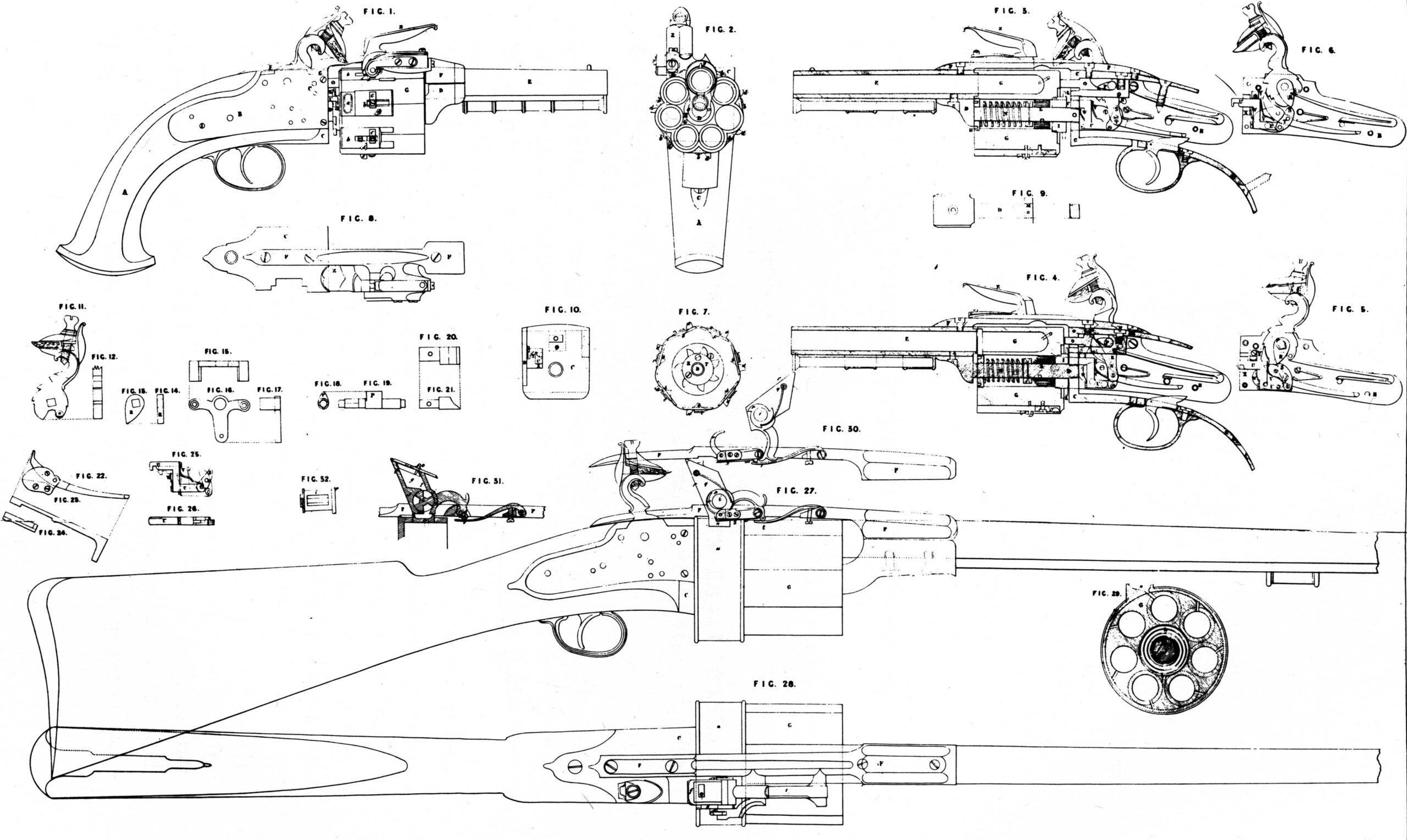
Fig. 1, is the side view of a pistol formed upon this construction; Fig. 2, and end view of the same; and Fig. 3, a section through the middle of it, viewed on the opposite side to Fig. 1. Fig. 4, is another section similar to Fig. 3, excepting that the situations of several parts of the movements are changed, as will be described hereafter. Figs. 5, and 6, are also introduced to shew the different situations of particular parts of the lock in performing their several offices. Other figures, from Fig. 7 to Fig. 26 inclusive, are also added to explain the detail of the several parts. A, Figs. 1, and 2, is the wooden stock of the pistol. B, a metal plate forming one side of a frame or case to contain the parts of the lock and other movements, to be particularized hereafter. C, is another metal plate with straps forming the top end, and bottom of this frame, which is firmly secured to the stock. A, by screws. Into the end of the frame C, is screwed the axis D, at the other end of which is an elevated off-set having a hollow made in its upper part, into which one end of the long barrel E, which is open at both ends, is received and secured by a screw. To the top of the frame C, is secured the elevated brace F, having also at its other end a hollow to fit the end of the long barrel E, and to which it is also joined by a screw; and thus the long barrel E, is firmly united to the frame C. Upon the axis D, revolves a number of short barrels or chambers G, arranged in a circular manner, and at equal distances around the axis. One end of each of these short barrels is closed, and they are of sufficient capacity to contain the charges of gunpowder, shot, or ball intended to be used. These short barrels may either be made of iron, or of any other fit metal or composition of metals, in separate tubes, and afterwards firmly united together, or they may be made out of one solid mass of metal properly bored and shaped into form. A cylindrical hole is made through the centre of this set of short barrels, into the fore end of which is screwed a nut H, having a cylindrical hole in its centre, through which the axis D passes, and into the opposite end of it another nut I, is screwed, with a cylindrical hole also in its centre, fitted to the axis. This nut I, is prevented from becoming unscrewed by means of a steady pin screwed into the joint between the male and the female screw. To the nut I, is screwed a plate or wheel K, having a number of teeth equidistant around it, corresponding to the number of short barrels used, the use of which teeth will be described hereafter. On the axis is fastened one end of a spiral spring L, similar to the main spring of a clock or watch, the other end of which is secured to the inner part of the cylindrical hole within the set of short barrels, and which spring, when wound up, has a tendency to cause the barrels to revolve in a circular direction. A boss or ring M, is also fixed upon the axis D, by means of a pin passed through it, against which boss one end of an helical spring N, placed upon the axis D, presses, the other end of it pressing against the nut H, in the fore end of the set of short barrel G, and thus gives it a tendency to thrust or push outwardly, so as to cause a recess made in the end of each short barrel to fit upon a shoulder made upon the end of the long barrel as they pass it in succession, and thereby to make a close joint with it ready to be discharged. In order to prevent the short barrel from recoiling during the discharge, a bolt 0 is thrust against it by the action of a tooth P, formed upon the axis of the lock-tumbler, shewn in Fig. 3; that part of the axis opposite to the tooth P, being also supported by a bracket Q, firmly screwed to the top plate of the frame C, and rivetted to the end plate thereof. Another tooth, R fitted upon the square part of the axis of the tumbler, operates upon one end of a lever S, turning upon its fulcrum at T, to the other end of which is jointed the catch bolt U, so as to cause it to advance Ad recede alternately, and when advanced to catch or lay hold of that tooth of the wheel K, which may happen to be opposite to it, and being withdrawn to bring the set of short barrels along with it, until that one which was engaged in or jointed with the long barrel becomes sufficiently separated from it to allow the spiral spring L, to cause it to revolve far enough for the next short barrel in succession to take its place, which it does by the pressure exerted by the helical spring N, against the set of short barrels, and by the catch bolt U, slipping off the tooth of the wheel K, in consequence of the circular motion of the barrels, and thereby permitting the recess in the approaching short barrel to slip upon the shoulder on the end of the long barrel.
Fig. 1, represents the pistol as just discharged, with the catch bolt U, hooked upon one of the teeth of the wheel K.
Fig. 3, is a section of the pistol in this situation, to shew the tooth R, lying ready to act upon the lever S, and pull back the catch bolt U.
Fig. 4., shews the cock a little raised, the tooth R, being engaged in pushing forwards the end of the lever S, and thereby drawing back the catch bolt U, and the set of short barrels, until that which was united with the long barrel has become disengaged from it. The tooth of the wheel K disengages itself from the catch bolt U, by the action of the spiral spring, and the cock will then be at liberty to be brought to the half cock, and the catch bolt withdrawn so far as to let the next tooth of the wheel R pass by it, and the next short barrel will then be at liberty to engage itself with the long barrel by the action of the helical spring N.
In bringing the cock from the half cock to the full cock, the tooth R depresses the lever S, until it can pass over it, at the same time compressing the spring V, which is attached to the catch bolt U; but when brought to full cock, as shewn in Fig. 5, the tooth R will have passed over the lever S, and by the reaction of the spring V the lever will be raised, so as to be acted upon by the tooth R, in the opposite direction when the cock is discharged. By the time it has arrived at the situation of half cock the tooth R will have pushed back the lever S, and moved the catch bolt U, forwards, until the spring W (also fixed to the catch bolt) acts against the stud X, and as the cock moves further down the lever S is still more depressed, so that the tooth R, is just ready to pass over it; and when in this situation, the end of the spring W, being pressed against the stud X, which is above the fulcrum T, upon which the lever S moves, it causes the catch bolt U to rise up to the upper side of the cap or cavity through which it passes, at the same time receiving the spring Y, which acts on the top of it, as shewn in Fig. 6; the catch bolt is thus lifted up sufficiently high to pass over the before-mentioned tooth of the wheel K. When the cock has descended a little more the tooth R will have passed the end of the lever S, and by the reaction of the spring W, the lever S will be raised to its first situation, as shewn in Fig. 3, and at the same time, by the reaction of the spring Y, the catch bolt U, will be depressed and hooked upon the tooth of the wheel K, ready to again bring forwards the short barrels, as before described. When the cock is quite down, as shewn in Fig. 3, and the discharge may be taking place, it will be observed that the point of the tooth P is depressed below the centre of the axis of the tumbler: and the greater is the effort made by the discharge of the piece against the bolt 0, to cause it to recede, so much the more does it prevent the tooth P from rising out of the recess in the end of the bolt 0, which is below the centre ofthe axis of the tooth, the bolt itself being supported upon the bracket Q. When the cock is raised the tooth P is lifted out of the recess in the end of the bolt 0, and permits it to slide back by the pressure of the short barrels against it, as shewn in Fig. 4 the sear and other parts of the lock not described, being common to other locks, need not be particularized here; I can apply either the usual hammer or one of the magazine hammers (to be herein-after described) to this lock. The hammer Z, is united to the elevated brace F, (instead of to the lock plate as usual) as shewn in Fig. 1, and 8. Each short barrel has a separate pan a, and a sliding cover b, fitted to it, moving in dovetailed grooves, and regulated by the spring c, so as to move freely, but not too easily, so as to be affected by the recoil in firing the piece. Each sliding cover has also a tooth or stud d, upon it, against which the toe e, of the hammer acts on shutting the pan, so as to cause the cover to slide back, the hammer itself then covering the priming ready to receive the fire fromthe flint. In order to use this weapon the short barrels or chambers must each receive a charge of gunpowder, and either shot or ball, as may be required. The pans also must be filled with prime, and the sliding covers shut upon it. All the short barrels but one may be loaded, and that one, namely, that which is engaged in the long barrel, will be disengaged from it on winding up the spring L, by turning the short barrels round in the contrary direction to that in which they move when fired, the remaining short barrel may then be loaded and primed, and the piece is ready to fire off each charge in succession by merely cocking the lock, shutting the hammer, and discharging the piece.
Fig. 27, is a side view, and Fig. 28, a top view of a gun, fitted up with a lock and its appendages of the construction before described as applied to the pistol, but with a magazine hammer and one pan only, which serves all the short barrels as they resolve. This magazine hammer f, has a chamber g, Fig. 31, made at the back of it, to hold a sufficient quantity of gunpowder to fire off the number of barrels required. At the lower part of the chamber is fitted a cylinder i, shewn separately at Figure 32, having a number of equidistant cavities j, j, j, around it, and each sufficiently large to receive a supply of gunpowder for a priming. This cylinder communicates with the chamber by the opening 1, at the bottom of it; and underneath it is another opening m, which delivers the gunpowder it has received into the pan n; a sliding cover o, with a study and regulating spring in the inside of the chamber, closes it. On one end of the cylinder is fitted a ratchet wheel p, Figs. 27, and 30, having teeth corresponding to the number of cavities in the cylinder, and a spring q, to retain it in the required situation. This ratched wheel meets a click r, jointed to the elevated brace f, having a spring s, acting upon it, and which click causes the cylinder to turn on shutting the pan until the next cavity in succession is brought over the pan, as shewn in Fig. 31, and delivers its priming into the pan, whilst at the Sam time another cavity is receiving another priming from the chamber, as is likewise shewn in Fig. 31. The toe of the hammer is acted upon by the spring t, in the manner represented in Figs. 27, and 30. The pan n, is attached to a metal hoop or cylinder a, at the end of which is a plate with a hole in the middle of it to permit the axis and bolts to pass through; this plate is firmly secured to the end plate of the frame c, by means of screws. Within the hoop u, the set of short barrels revolves, the interstices between the mat that end being filled up or left solid, so as to form a cylindrical surface nearly filling the hoop, so as not to permit the gunpowder to pass out of the barrels through the touch holes, nor the flame to communicate from one barrel to another. Within this hoop the short barrels are capable of moving in all the various directions, the same as if it was not there.
Fig. 29, represents the set of short barrels G, within the hoop u, and the situation of the pan n, upon it communicating with one of the touch holes. Fig. 7, is the set of short barrels viewed from the opposite end in Fig. 9, shews the axis D, separate. Fig. 10, is the end of the lock frame C. Fig. 11, is a side view of the cock; and Fig. 12, shews its thickness. Fig. 13, is the tooth R, of which Fig. 14, shews the thickness. Fig. 15, 16, & 17, are different views of the bridle of the tumbler, which is situated when in use near the middle of it, between the teeth P, and R. Figs. 18, and 19, are an end and front view of the axis of the tumbler and tooth P. Figs. 20 and 21, are a top and side view of the bolt 0. Fig. 22, is a side view of the sear and sear bridle. Fig. 23, is an edge view of the sear. Fig. 24, an edge view of the sear bridle; and Fig. 25, is a side of the lever S, and catch bolt U, with its springs W and V, the dotted lines shewing other situations of the different parts, as already described. Fig. 26, is an edge view of Fig. 25.