
US 346327
UNITED STATES PATENT OFFICE.
JOHN T. SMITH, OF ROCKFALL CONNECTICUT.
REVOLVER.
SPECIFICATION forming part of Letters Patent No.346,327, dated July 27, 1886. Application filed January 18, 1886. Serial No. 188,861. (No model.)
To all whom it may concern:
Be it known that I, JOHN T. SMITH, of Rockfall, in the county of Middlesex and State of Connecticut, have invented a new Improvement in Revolvers; and I do hereby declare the following, when taken in connection with accompanying drawings and the letters of reference marked thereon, to be a full, clear, and exact description of the same, and which said drawings constitute part of this specification, and represent, in–
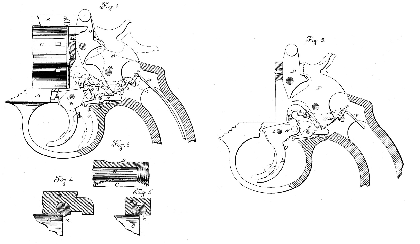
Figure 1, a sectional side view of so much of the revolver as necessary to illustrate the invention, solid lines indicating the normal position of the parts and broken lines the position of the parts when set at full-cock by hand; Fig. 2, the same view showing in solid lines the position of the parts immediately after discharge and as the trigger is approaching its extreme forward or normal position, and broken lines indicating the retreating movement of the hammer as the trigger completes its movement to its normal position; Fig. 3, a transverse section through the arm over the cylinder, showing a side view of the cylinder-holding pin; Fig. 4, a longitudinal central section through the arm, showing the pin in the securing position; Fig. 5, the same as Fig. 4, showing the pin when turned to release the cylinder.
This invention relates to an improvement in that class of revolvers in which the barrel and cylinder are hinged to the frame forward of the cylinder, and adapted to be turned on the said hinge to raise the cylinder sofar from its place in the frame that it may be removed, and also to that class of revolver lock mechanisms in which the hammer is adapted to be cocked by the pull of the trigger or by hand, as the case may be, and is an improvement upon the invention described in another application, Serial No. 164,299, the object of the present invention being, first, a simple device by which the cylinder may be held in its place in the frame, and yet easily removed as occasion may require, and also to produce a re bounding movement of the hammer through the instrumentality of the lever between the hammer and the trigger; and the invention consists in the construction hereinafter described, and particularly recited in the claims.
A represents the frame, within which the lock mechanism is arranged, and to which the part of the frame carrying the cylinder is hinged in the usual manner, the hinge not being shown.
B represents the arm, which extends from the barrel portion of the frame over the cylinder C, and adapted to be engaged by the latch D, in the usual manner. When the barrel is turned upon its hinge to open the cylinder for the introduction of cartridges or removal of the shells, some device is necessary to prevent the escape of the cylinder from the spindle upon which it revolves. To this end I introduce a pin, E, transversely through the arm B. The underside of the arm is concave in transverse section, corresponding to the shape of the cylinder, as seen in Fig. 3, and the pin is introduced with relation to the cylinder so that a portion of the cylindrical surface of the pin will stand below the under central surface of the arm. The axis of the pin is best arranged substantially in the plane of the rear end of the cylinder, as seen in Fig. 4. On one side the pin is recessed to form a shoulder, a. This recess is of a depth equal to the projection of the cylindrical surface of the pin below the underside of the arm, and so that when the pin is turned to bring that recess below, as seen in Fig. 5, the recessed surface of the pin will be above the cylinder, and so that the cylinder may be withdrawn or replaced, and when the cylinder is in place the pin is turned to bring the shoulder a against the rear end of the cylinder, as seen in Fig. 4, and thus serve as a means for securing the cylinder. This pin is best made in the form of a screw, as seen in Fig. 3, with a nick in one end, by which it may be conveniently turned.
F is the hammer, hung upon a pivot, G; H, the trigger, hung upon its pivot I; J, the sear, hung upon its pivot K, and provided with the usual sear-spring; L, the lever, hung in the hammer upon a pivot, M, below the pivot on which the hammer turns. This lever extends to the rear, and its rear arm is hung to the mainspring N by a link, O. The lever extends forward over the trigger, as seen in Fig. 2, its forward end adapted to be engaged by a shoulder, P, on the trigger, and so that by pulling the trigger the movement of the trigger is communicated to the lever, and thence to the hammer, so that by means of the trigger the hammer may be brought to full-cock, as in the application before referred to, and there discharged without engagement of the sear, the sear being held out of engagement by the auxiliary trigger R, hung in the principal trigger, not necessary to be particularly described in this application.
Many times it is desirable to cock the hammer by hand instead of by the trigger, and in my previous application I made provision for so doing by an engagement of a shoulder on the lever with a corresponding shoulder on the trigger; but I find it desirable to make a more positive engagement between the lever and the trigger when cocking by hand. To that end I construct the lever with a shoulder, b, upon its under side, near the forward end, and with a second shoulder, d, in rear of the shoulder b, and I construct the trigger with corresponding shoulders, e and f, so that as the hammer is turned backward, as from the position seen in Fig. 2, the first shoulder, b, engages the shoulder e, and then as the rear movement is continued the shoulder d engages the shoulder f, while the shoulder b may escape from the shoulder e. Thus the second shoulder takes a strong bearing upon the trigger, and makes a firm connection between the hammer and trigger in the action of cocking by hand. The forward end or nose, g, of the lever is turned downward to engage the shoulder P on the trigger, as shown, and so that in cocking by the trigger the pull is made upon the trigger through the nose g. When the hammer is cocked by hand, as indicated in broken lines, Fig. 2, the full-cock notch h engages the nose of the sear, as indicated in broken lines, Fig. 2. The trigger at that time is thrown to its extreme rear position, as also seen in Fig. 2, preparatory to discharge. If in this condition (seen in broken lines, Fig. 2) the auxiliary trigger be pulled, the sear is turned from its engagement with the hammer, and the hammer flies forward, drawing the lever L backward, while the trigger is still held by the finger, and into the position seen in Fig. 1. Then when the finger is released the trigger moves forward, leaving the sear free, and, rising, the nose of the sear engages a shoulder, i, on the lever L below its fulcrum or pivot M, and this engagement is made before the nose g of the lever can pass over the shoulder P on the trigger, and as seen in Fig. 1. Then as the trigger continues its forward movement, the shoulder P escapes from the nose g of the lever, thereby permitting the forward end of the lever to turn downward under the action of the mainspring, as indicated in broken lines, Fig. 1. In thus turning the lever L its shoulder i acts upon the nose of the sear as a fixed fulcrum; hence as the lever turns upon that fulcrum (which is below the pivot M, between the hammer and lever) it necessarily follows that the pivot M will be drawn forward, as indicated in broken lines, Fig. 1, and such forward movement of the pivot turns the hammer backward, as also indicated in broken lines, Fig. 1, and thus gives to the hammer, under the action of the mainspring, a retreating movement sufficiently far to take it from possible contact with the firing-pin. The same action occurs whether the hammer be cocked by hand or by the trigger. The hammer can only rest upon the firing pin so long as the trigger be held in its rear position. When the trigger is free, it is thrown forward, so that the nose of the lever L can escape over the shoulder P, and necessarily produce the retreating movement of the hammer.
I am aware that the cylinder has been held in place by a shoulder formed on the latch which is hinged to the arm above the cylinder, said latch being adapted to engage the handle portion of the frame; but in such construction the cylinder is released every time the latch is raised to disengage the barrel portion of the frame from the handle portion, in which case the cylinder is liable to slip from its position and interfere with the proper working of the arm. I therefore do not wish to be understood as claiming, broadly, a shoulder adapted to be brought into or removed from the rear face of the cylinder, the essential feature of my invention being the pin transversely through the arm above the cylinder adapted to be rotated, and constructed with a recess to form a shoulder, which said shoulder, under the rotation of the pin, may be brought against the rear face of the cylinder to serve as a stop, or upon a return of the pin the shoulder will be taken from its bearing against the cylinder, the recess then permitting the removal of the cylinder and the said pin independent of the securing device between the two parts of the frame.
I claim–
1. The herein-described improvement in revolvers, consisting in the cylindrical pin E transversely through the arm B above the cylinder, the said pin recessed upon one side to form a shoulder, a, substantially as described, and whereby the said shoulder may be brought against the rear end of the cylinder to hold it in place or turned therefrom for the removal of the cylinder.
2. The combination of the hammer F, the trigger H, the sear J between the said trigger and hammer, and adapted to engage the full-cock notch of the hammer, the lever L, hung upon a pivot in the hammer below the pivot of the hammer, one arm extending rearward and hung to the mainspring, the other arm extending forward and constructed with the two shoulders b d, the one in rear of the other, and the trigger constructed with corresponding shoulders, e f, with which the said two shoulders b d on the said lever are adapted to engage in cocking by hand, substantially as described.
3. The combination of the hammer F, the trigger H, the sear J, adapted to engage said hammer at full-cock, the lever L, hung in the hammer upon a pivot below the pivot upon which the hammer turns, one arm of said lever extending rearward and hung to the main spring, the other arm extending forward and its forward end turned downward to form a nose, g, the trigger constructed with a shoulder, P, over which said nose g is adapted to pass when the trigger is free, the said lever also constructed with a shoulder, i, below its pivot, and adapted to engage the sear when the hammer is thrown forward under the pull of the trigger, substantially as described, and where by, as the nose of the said lever L escapes over the shoulder P on the hammer, the sear, engaging the said shoulder i on the lever, forms a fixed fulcrum upon which said lever may turn under the action of the mainspring and impart retreating movement to the hammer.
JOHN T. SMITH.
Witnesses:
ARTHUR. B. CALEF,
ARTHUR. B. CALEF, Jr.