
US 301649
UNITED STATES PATENT OFFICE.
JEAN WARNANT, OF LIEGE, BELGIUM, ASSIGNOR TO COLTS PATENT FIRE-ARMS MANUFACTURING COMPANY, OF HARTFORD, CONNECTICUT.
REVOLVER.
SPECIFICATION forming part of Letters Patent No. 301,649, dated July 8, 1884.
Application filed April 7, 1884. (No model.) Patented in Belgium July 19, 1883, No. 62,109.
To all whom, it may concern:
Be it known that I, JEAN WARNANT, of Liege, Belgium, have invented a new Improvement in Revolvers; and I do hereby declare the following, when taken in connection with accompanying drawings and the letters of reference marked thereon, to be a full, clear, and exact description of the same, and which said drawings constitute part of this specification, and represent, in–
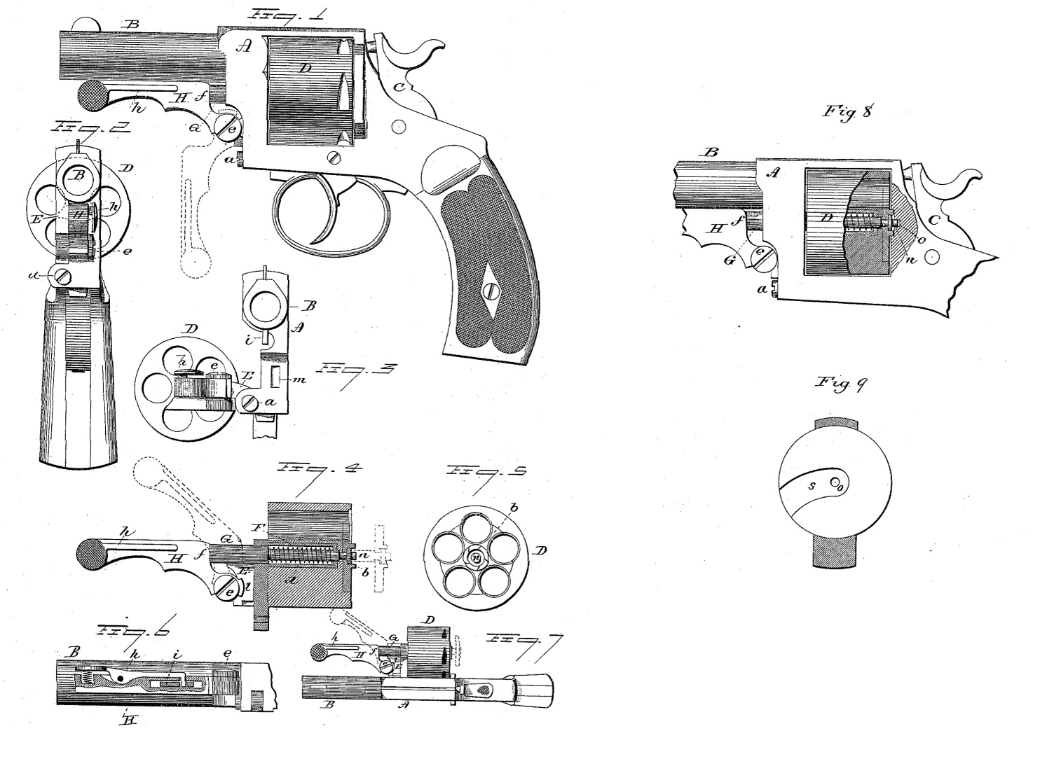
Figure 1, a side view, all the parts in their normal condition; Fig. 2, a front view of the same; Fig. 3, a front end view, the cylinder turned from its recess in the receiver; Fig. 4, a longitudinal sectional view; Fig. 5, a rear view of the cylinder, showing the ejector; Fig. 6, an under side sectional view of the lever and barrel, showing the latching device; Fig. 7, a top view of the cylinder turned from its recess in the receiver, reduced scale; Fig. 8, a sectional side view, showing the spindle as engaged with the frame at the rear to lock the cylinder in place; Fig. 9, a vertical section showing the front face of the recoil-plate.
This invention relates to an improvement in that class of revolvers in which the cylinder is hinged to the frame, so as to swing from its recess in the frame for the purpose of loading the chambers or ejecting the exploded shells, and particularly to that class in which the cylinder is hinged upon an axis parallel with its own, so as to swing in a plane at right angles to its own axis, the object of the invention being to combine with the cylinder and its swinging frame a lever, which, while it serves to lock the cylinder when in its position in the frame, will also serve as a device for operating the ejector, and in such construction, as more fully hereinafter described, my invention consists.
A represents the receiver, to the forward end of which the barrel B is attached, and provided with the usual hammer, C, and lock mechanism at the rear, the receiver constructed with the usual recess for the cylinder D. Upon the right-hand side of the receiver, and forward of the cylinder-opening, a frame, E, is hinged below the cylinder-opening, as at a, the axis of the hinge being parallel with the axis of the cylinder. The frame E carries a spindle, F, upon which the cylinder is arranged, and which spindle forms the axis upon which the cylinder will rotate. The forward part of the receiver is recessed to receive the frame E when turned into its closed or working position, as seen in Figs. 1 and 2. The spindle F does not extend quite through the cylinder, as seen in Fig. 4, and is made hollow. Through the spindle the ejector-rod G is concentrically arranged, extending through the cylinder to the rear, where it is fitted with what is commonly known as the “star-ejector” b, as seen in Fig. 5. The rod G extends through the frame forward, and within the hollow spindle F is of smaller diameter than at its forward end, so as to form a recess in the spindle around the ejector-rod, and into this recess a spring, d, is introduced, the action of which is to hold the ejector-rod in its extreme forward position, but yet yield for the rear movement of the ejector-rod, as seen in broken lines, Fig. 4.
To the frame E, below the center, a lever, H, is hung, as at e, the lever being provided with a shoulder, f, above, in line with the ejector-rod. This lever, in its normal position, extends forward along the underside of the barrel, as seen in Fig. 1, and is provided at its forward end with a latch, h, to engage a corresponding lug, i, on the barrel, as seen in Fig. 6, and so as to lock the lever when in its closed or normal position, as seen in Fig. 1. When the lever is disengaged from its locked position beneath the barrel, it is first turned down, as seen in broken lines, Fig. 1, then the lever moved to the left, the cylinder will be thrown out upon its hinge, as seen in Fig. 3, so as to leave all the chambers open at the rear. The cartridges may now be inserted, the cylinder returned, and the lever H brought to its locked position. Then the arm is ready for firing, and after firing the lever H is again disengaged and turned down, the cylinder thrown out, as before, to clear the heads of the exploded shells, and when so thrown out the lever H is turned upon its pivot to bring the shoulder f against the ejector-rod, and then by a continued swinging movement of the lever, as indicated in broken lines, Fig. 7, the ejector-rod will be caused to expel the exploded shells.
To lock the cylinder in its place, the lever H is constructed with a cam-like projection, l, on its hub, and the receiver with a corresponding recess, m, and so that after the cylinder has been turned to its place, the lever H being down, as indicated in broken lines, Fig. 1, on the return of the lever to its locking position the projection l will enter the recess m in the receiver, and thereby lock the parts in their normal position.
As a further lock, the ejector-rod is constructed so as to have a slight movement in an axial direction independent of the star piece b-that is, so that when the ejector-rod stands in its extreme forward position it will be permitted a slight rear movement before it will act upon the star-piece. The extreme rear end of the ejector-rod forms a central or concentric stud, n, at the rear of the cylinder, and in the receiver at the rear end of the cylinder-recess is a central hole, o, corresponding to the stud n on the end of the ejector rod. When the cylinder is thrown into its closed position, and before the lever H is turned up, the ejector-rod stands in its extreme forward position, so that the stud n enters the cylinder-recess; but as the lever H is turned into its locking position, and just before it reaches that position, the shoulder it strikes the forward end of the ejector – rod and forces it rearward to carry the stud n into the hole o at the rear of the receiver, as seen in Fig. 8, which operation practically engages the spindle of the cylinder with the receiver at the rear, and which, together with the lock at the front, as heretofore described, firmly engages the cylinder with the receiver, so as to avoid all possible accidents from the displacement of the cylinder. The front face of the recoil-plate is recessed, as at s, around the center outward, so as to permit the ratchet of the cylinder to pass out and in.
I claim–
1. In a revolver, the combination of a frame forward of the cylinder, hinged to the receiver to swing upon an axis which is parallel with the axis of the cylinder, said frame carrying the cylinder spindle, the cylinder arranged on said spindle, an ejector-rod concentrically through the cylinder and spindle, carrying the star-ejector at the rear, a spring to force the ejector-rod into its forward or closed position, a lever hinged to said frame, and so as to swing in a plane parallel with the axis of the cylinder, and arranged to bear upon the ejector-rod and impart to said rod its rear or ejecting movement, substantially as described.
2. In a revolver, the combination of a frame forward of the cylinder, hinged to the receiver to swing upon an axis which is parallel with the axis of the cylinder, said frame carrying the cylinder-spindle, the cylinder arranged on said spindle, an ejector-rod concentrically through the cylinder and spindle, carrying the star-ejector at the rear, a spring to force the ejector-rod into its forward or closed position, a lever hinged to said frame, and so as to swing in a plane parallel with the axis of the cylinder, and arranged to bear upon the ejector-rod, and impart to said rod its rear or ejecting movement, and a latch arranged in said lever to lock it in its closed position, substantially as described.
3. In a revolver, the combination of a frame forward of the cylinder, hinged to the receiver to swing upon an axis which is parallel with the axis of the cylinder, said frame carrying the cylinder-spindle, the cylinder arranged on said spindle, an ejector-rod concentrically through the cylinder and spindle, carrying the star-ejector at the rear, a spring to force the ejector-rod into its forward or closed position, a lever hinged to said frame, and so as to swing in a plane parallel with the axis of the cylinder, and arranged to bear upon the ejector rod and impart to said rod its rear or ejecting movement, the said lever constructed with a projection, l, and the receiver with a corresponding recess, m, substantially as described.
4. The combination of the frame E, hinged to the receiver upon an axis which is parallel with the axis of the cylinder, and carrying the hollow spindle F, the cylinder arranged on said spindle, the lever H, hinged to said frame to swing in a plane parallel with the axis of the cylinder, the ejector-rod G, arranged concentrically through the cylinder and spindle, a spring serving to hold the ejector-rod in its extreme forward position, the star-ejector b at the rear, the ejector-rod passing through said star and constructed for a certain longitudinal movement independent of said star, its rear end forming the stud n, with a corresponding hole, a, in the receiver, and so that in the last part of the closing movement of said lever H the said ejector-rod will be forced rearward and cause the said stud to enter the hole o, substantially as described.
JEAN WARNANT.
Witnesses:
H. SCHWERS,
J. W. WEMAM.