
Britain 5972
A.D. 1885, 15t May. № 5972.
Improved Lock Mechanism for Revolvers.
COMPLETE SPECIFICATION.
I, Gustaf Envall, of Linndgatan No 20, Stockholm, Sweden, Major in the Swedish Army, do hereby declare the nature of said invention for “Improved lock mechanism for revolvers” and in what manner the same is to be performed, to be particularly described and ascertained in and by the following statement:—
In the automatically cocking revolvers hitherto in use, it has been necessary before taking aim to bring them to full cock with the thumb as in ordinary pistols, in order to ensure a good aim. With rapid firing, however, when there is no time of cocking beforehand, the cocking must be done and the shot fired by a single pull of the forefinger. Under these circumstances the main spring offers a great resistance, and the finger having to travel a distance of 13 to 14 millimetres the pull must be effected almost instantaneously and a trembling of the weapon can scarcely be prevented. It is often remarked that at very short distances persons fire successively several times without making a hit or only occasioning a slight wound.
The object of this invention is the production of a lock mechanism affording greater accuracy, particularly in rapid firing, by the use of two triggers, one under the revolver, whereby the weapon is cocked but by which it cannot be fired, and another at the top whereby the shot is fired by the thumb, This mode of operation has the advantage that the revolver is not brought out of position at the very moment of firing.
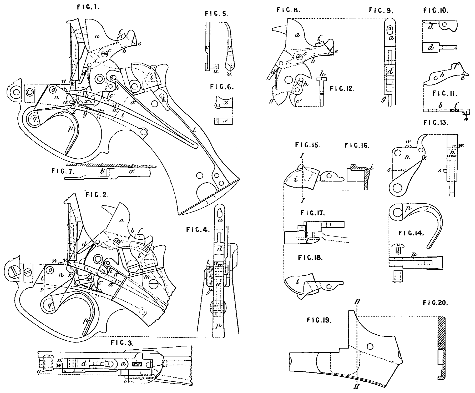
On the accompanying sheet of drawings Fig 1 represents a side view of the lock and the rear part of the revolver with the side plate and cheek taken away, the revolver being safety cocked, Fig 2 represents a side view of the lock or the mechanism with the side-plate removed, the hammer being brought to the full cock. Fig 3 is a plan, Fig 4 is a cross section in front of the hammer a and the spanner showing them when brought to the full, cock. The other figures represent details of the mechanism, Fig 5 represents, viewed from two sides, the pawl v, by which the revolver drum is turned. Fig 6 is a top view and a side view of the catch x. Fig 7 is the fore part of the undermost arm a¹ of the main spring, viewed from above. Fig 8 represents a side view of the hammer a and Fig 9 a front view of the same. Figs 10, 11 and 12 represent the moveable parts of the hammer removed, viz, Fig 10 the tongue d, Fig 11 the lever b, each shown from two sides and Fig 12 a front view of the main spring link h. Fig 18 is a front and side view of the spanner proper n and Fig 14 a side and top view of the arm p of the spanner. Fig 15 is a side view of the trigger 7 seen from without; Fig 16 is a section of the same along the line I, I of Fig 15. Fig 17 is the same seen from above and Fig 18 the same from the inner side. Fig 19 is a side view of the side plate and Fig 20 the same in section along the line II— II of Fig 19.
Similar letters of reference indicate corresponding parts in all the figures.
In this lock mechanism the hammer a is provided with a lever b passing through a hole in the hammer and pivotted at c. The shorter arm of this lever is situate below a backwardly projecting tail of the tongue d; the longer arm is provided with a tappet e projecting from the end of the comb of the cock, and also with a projection f extending a little outside the-inner rounding of the comb. The hammer is further provided with a shoulder or rounded surface g at the one side. The main spring link h, embraced by the top arm a¹¹ of the main spring, is extended downwards.
The trigger i situate at the top of the butt, is pivotted at k and actuated by the spring l and kept in position by the downwardly bent end of the plate m (shown by the dotted lines in the Fig 17).
The spanner n, pivotted on the pin o, the arm p of which is pivotted thereon, is provided with a stop s, which by encountering a fixed part of the revolver body t limits its motion. On the spanner n is the pawl v pivotted on its pin u, by which pawl the drum (not shown on the drawing) is turned round, w is a shoulder, which at the full cock, falls in a slot in the drum, thus fixing it.
a is a catch, which actuated by a little spring y, is pressed into the slit z on the spanner when the hammer is brought to the full cock.
The mechanism works in the following manner: In order to cock the hammer, the arm of the spanner is pulled back with the forefinger (or the middle finger) whereby the spanner proper n pivots on the pin o until the stop s encounters the lower edge of the revolver body and the catch a is pressed into the slit z. The spanner n is now locked by the catch x and the stop s and the hammer has been brought to the full cock as shown in Fig 2, The pawl v has meanwhile turned the drum the requisite angle, and the shoulder w of the spanner fixes the drum in the usual manner.
Now a sure aim being taken, the firing is effected by pressing the trigger i downwards by means of the thumb. The trigger actuates then the lever b and this turns the tongue d from its support against the spanner n and the upper arm at of the main spring causes the hammer to fall down. On falling, the shoulder g on the hammer presses the catch x out of the slit z of the spanner n, which becomes free.
When the shot has been fired, but not before, the forefinger lets off, when the bottom arm a¹¹ of the main spring reposing upon the pawl v brings back the spanner into its former position (see Fig 1). At the same time the shoulder b¹ of the main spring arm a¹ glides along the curved surface c¹ of the downwardly extending part of the main spring link h and presses the hammer to the safety bend (shown in Fig 1).
If, after cocking, the shot is not to be fired, the hammer may be let down in the usual manner with the thumb by pressing in the projection f, The hammer moves then automatically into the safety position.
Having now particularly described and ascertained the nature of my said invention and in what manner the same is to be performed, I declare that what I claim is
1. The use in a revolver of a lock mechanism in which the hammer is spanned and locked at full cock by pulling the arm of the spanner backwards by the fore-finger and the firing is effected by pressing the thumb on a trigger situated at the top of the butt, substantially as described.
2. In a revolver mechanism such as referred to in the previous claim, the use of the hammer a provided with a lever b, whereby the moveable tongue d can be moved and with a shoulder or plane g for the catch x substantially as described.
3. In a revolver mechanism such as referred to in the first claim the use of the moveable trigger i kept in position by a spring, which trigger acting through the lever b of the hammer, turns the tongue d from its support against the spanner n substantially as described.
4. In a revolver mechanism such as referred to in the first claim the use of the moveable catch x which in cocking the hammer is pressed by a spring y into the slit z of the spanner n thus locking it, and which in letting down the hammer, is brought out of the slit by means of the shoulder g on the hammer substantially as described.
5. In a revolver mechanism such as referred to in the first claim the use of the spanner n with the stop s the slit z and the arm p substantially as described.
6. The improved revolver mechanism, constructed, arranged and operating substantially as described with reference to the drawings.
Dated this 15th day of May 1885.
W. LLOYD WISE,
46, Lincoln’s Inn Fields, London, W.C.,
Applicant’s Agent.