
Britain 4070
MEMORANDUM.
WEBLEY AND CARTER’S SPECIFICATION, № 4070, A.D. 1885.
Certain clerical errors in the Original Specification having been amended by the Patentee with the consent of the Comptroller, the printed Specification will now read as shown below:—
Page 3, line 8, to read
‘security in the mechanism used for fastening the extension rib of extracting revolvers’
Page 8, line 25, for “Pivotted” read “Pivoted”
Page 4, lines 32 and 33, for “raiser” read “lifter”
Page 4, line 33, for “raised” read “lifter”
Page 5, line 1, for “t” read “l”
Note.— The word “breach” (page 4, line 34) is a printer’s error and should read “Breast”
Patent Office,
19th April 1886.
A.D. 1885, 31st March. № 4070.
PROVISIONAL SPECIFICATION.
Improvements in Revolving Firearms.
We Henry Webley, of Weaman Street, Birmingham of the Firm of P Webley & Son, Gun and Pistol Manufacturers, and John Carter, of 33 Ford Street, Birmingham, Action Filer, do hereby declare the nature of our invention for “Improvements in Revolving Fire-arms” to be as follows—
The first object of our Invention is to attain greater solidity, strength, and security in the mechanism used for fastening the extension rib of extracting revolvers to the standing breech, to guard against the blowing open of the weapon when firing, and to enable heavy charges to be used with safety
We cut a slotted opening in a vertical direction through the rear end of the extension rib, When the barrel 1s closed as for firing, this slotted opening drops over and around a vertical lug on the standing breech, the slotted opening in the extension rib, and the vertical lug on the standing breech being so formed as to fit together as nearly as may be like one solid piece. To lock the extension rib down to the standing breech, we use a stirrup fastener, turning on an axis passing through the standing breech. The cross bar of this stirrup fastener swings over the extension rib where the latter embraces the lug on the standing breech, and so prevents the extension rib from rising. One arm of the stirrup 1s longer than the other and forms a thumb lever for releasing the stirrup when opening the pistol
Our next improvement consists in raising and releasing the hammer in a novel way.
Pivoted to the trigger 1s & limb, which, by its upper end, operates on a projection on the breast of the hammer, by means of a bent which engages under the said projection. Above this bent the limb pivoted to the trigger terminates in a claw. This claw bears against the breast of the hammer, and, as the hammer approaches the point of pull-off, the claw gradually levers the bent of the before mentioned limb free from engagement with the hammer, and so causes the discharge of the fire-arm.
A very smooth and equal pull-off is thus secured.
Our third improvement consists in attaching the lower aide of the mainspring to a swivel, the said swivel having its other end attached to the trigger; or the lower side of the mainspring is caused to bear upon a lever, the said lever being attached to the said swivel, instead of attaching the mainspring directly to the said swivel. The end of the lever, other than that attached to the swivel, bears upon some part of the body of the firearm.
The effect of this improvement is to render easier and smoother the action of raising the hammer by the trigger, and also to secure a more vigorous and certain return of the trigger, when the pressure of the finger is eased.
Dated this Thirty first day of March, A.D. 1885.
For the Applicants,
W. E. GEDGE,
Agent.
COMPLETE SPECIFICATION.
Improvements in Revolving Fire Arms.
We Henry Webley of Weaman Street Birmingham, of the Firm of P Webley & Son Gun and Pistol Manufacturers, and John Carter of 38 Ford Street Birmingham Action Filer do hereby declare the nature of our invention for “Improvements in Revolving Fire Arms” and in what manner the same is to be performed, to be particularly described and ascertained in and by the following statement —
The first object of our Invention is to attain greater solidity, strength, and security in the mechanism used fastening the extension rib of extracting revolvers to the standing breech, to guard against the blowing open of the weapon when firing, and to enable heavy charges to be used with safety.
We cut a slotted opening in a vertical direction through the rear end of the extension rib
When the barrel is closed as for firing, this slotted opening drops over and around a vertical lug on the standing breech, the slotted opening in the extension rib, and the vertical lug on the standing breech being so formed as to fit together as nearly as may be like one solid piece To jock the extension rib down to the standing breech, we use a stirrup fastener, turning on an axis passing through the standing breech.
The cross bar of this stirrup fastener swings over the extension rib where the latter embraces the lug on the standing breech, and so prevents the extension rib from rising. One arm of the stirrup is longer than the other and forms a thumb lever fur releasing the stirrup when opening the pistol.
Our next improvement consists in raising and releasing the hammer in a novel way when operating the pistol by means of the trigger action.
Pivotted to the upper part of the trigger is a limb which, by its upper end operates on a projection on the breast of the hammer, by means of a bent which engages under the said projection. Above this bent the limb pivoted to the trigger terminates in a claw
We shall call this limb the hammer-lifter by reason of the function it performs
The claw on the hammer-lifter bears against the breast of the hammer, and, as the hammer approaches the point of pull-off, the claw gradually levers the bent of the hammer-lifter tree from engagement with the hammer, and so causes the discharge of the fire arm
When the trigger commences its movement, in using the trigger action for firing, the hammer lifter stands nearly at a tangent to the arc of movement of the pivot which attaches the hammer-lifter to the trigger, but, as the point of discharge 1s approached, the hammer-lifter approximates more and more to the radial line of the said arc of movement, and so balances the increasing compression of the main spring.
A very smooth and equal pull-off is thus secured, and even when using the trigger action the aim can easily:— be dwelt upon while the hammer is held suspended ready for and close to the release from the hammer-lifter
Our third improvement consists in attaching the lower side of the mainspring to a swivel, the said swivel having its other end attached to the trigger; or, the lower side of the mainspring 1s caused to bear against a lever, the said lever being at one end attached to the above mentioned swivel, and its other end having a fulcrum upon some part of the body or frame of the firearm.
The effect of this improvement is to render easier and smoother the action of raising the hammer by the trigger, and also to secure a more vigorous and certain return of the trigger when the pressure is released.
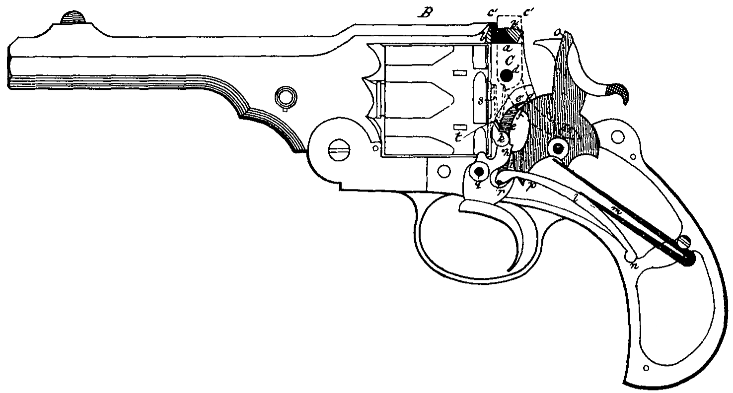
The accompanying drawing shews a revolving fire arm embodying the three before described improvements, The arm 1s shewn with the beech fastener closed and the weapon as on the point of discharge by use of the trigger action The frame of the pistol 1s shewn partly stripped, and part of the extension rib is in section.
The projecting lug a on the standing breech is shewn in black, and the extension rib B is shewn partly in section at b and b¹ It will be seen that the lug a is embraced on both sides and back and front by the extension rib B.
The stirrup fastener C— shewn by a dotted outline— turns on the axis d, and the cross bae c¹ locks over the part b¹ of the extension rib B, and against and partly over the lug a, Thus the extension rib and the lug are held firmly together, The arm c² of the stirrup fastener C forms a thumb lever for operating the said fastener.
When the hammer falls the raised forehead o comes nearly into contact with the cross bar c¹ of the stirrup fastener, and, if the said stirrup fastener be not securely locked overt the extension rib, the hammer cannot reach the primer of the cartridge, because the cross bar will arrest the motion of the falling hammer
It is therefore impossible to fire the charge unless the breach be securely fastened, and blowing open is thus guarded against
The construction of breech fastening sewn is capable of withstanding very heavy charges of powder, because the breech fastening cannot give way unless the extension rib be torn asunder or the lug a be torn from the breech
The stirrup fastener C is kept in position by a spring shewn in the drawing at S The spring t attached to the lifter bears against the hammer raiser, and performs the double function of pressing the lifter against the ratchet wheel on the cylinder, and the hammer raised against the breach of the hammer.
The hammer-lifter before described is shewn ate and is shaded by horizontal lines. The position of the firing mechanism shewn in the drawing is the moment of disengagement of the hammer from the hammer-lifter, at the point f, by reason of the pressure of the claw e¹ of the hammer lifter on the breast of the hammer at g It will be seen that at this moment of disengagement the point f, the pivot k— on which the hammer-lifter 1s carried by the trigger— and the pivot q of the trigger are nearly in a straight line, and the pull-off 1s thus easy and smooth
The swivel i— pivoted to the trigger at h and to the lever l at r— forms the means of causing the underside of the mainspring m and the trigger to act on each other through the lever l. The lever l is provided with a fulcrum at n in the frame.
It wall be seen that the pivot A moves in an are such as to graduate the action of the underside of the mainspring, and thus contribute materially to the smoothness of the pull-off
When the trigger 1s released from the controlling pressure of the finger the action of the underside of the mainspring causes a very vigorous return of the trigger to its normal position.
The lever l, when this return action takes place, also presses upon the hammer at p by means of a stud on the inner side of the said lever, and draws the hammer slightly back.
The lever may be dispensed with, if the underside of the mainspring be connected to the swivel i at the point r. In this case the underside of the mainspring must be prolonged and shaped like the lever from t to r and provided with a stud to act upon the hammer at p.
Having now particularly described and ascertained the nature of our said invention, and in what manner the same is to be performed, we declare that what we claim is
1. The fastening of the breech in a revolving firearm by the combination of the projecting lug, slotted extension rib, and stirrup fastener, as described and illustrated.
2. The combination of the projecting forehead on the hammer with the stirrup fastener for securing safety against firing the arm unless the breech be fastened.
3. The hammer-lifter as described and illustrated.
4. The combination of the swivel, lever and underside of the mainspring as described and illustrated.
5. The combination of the swivel and underside of mainspring without the lever as described.
6. The general construction of the breech closing mechanism as described and illustrated.
7. The general construction of the firing mechanism as described and illustrated.
8. The general combination of the breech closing mechanism and firing mechanism as described and illustrated.
Dated this Eighteenth day of December 1885.
For the Applicants,
W. E. GEDGE,
Agent.