
US 22005
UNITED STATES PATENT OFFICE.
ETHAN ALLEN, OF WORCESTER, MASSACHUSETTS.
IMPROVEMENT IN REVOVING FIRE-ARMS.
Specification forming part of Letters Patent No. 22,005, dated November 9, 1858.
To all whom it may concern:
Be it known that I, Ethan Allen, of the city and county of Worcester, and State of Massachusetts, have invented certain new and useful Improvements in the Construction of Repeating Fire-Arms; and I do hereby declare the following to be a full, clear, and exact description of the construction and operation of the same, reference being had to the accompanying drawings, in which drawings—
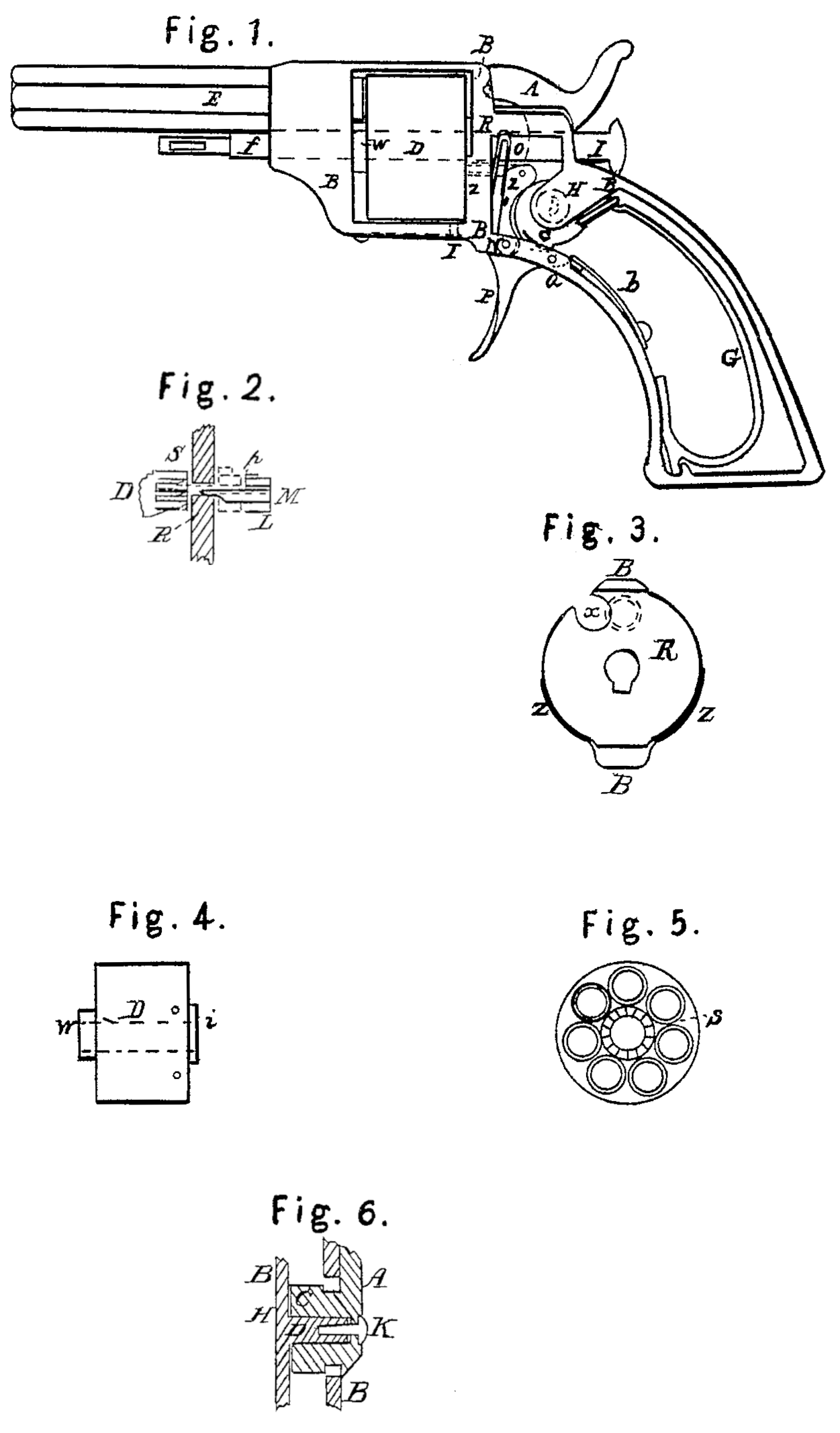
Figure 1 shows a side view with a part of the case removed to show the internal arrangement. The other figures represent parts hereinafter to be described, the same letters denoting the same parts where they occur in all.
In Fig. 1, A represents the hammer; C, the tumbler; B, the case or frame; D, the cylinder; E, the barrel; F, the trigger; G, the mainspring; I, the pin on which the cylinder D turns.
To support the tumbler C and hammer A, a projection, H, Fig. 1, is made solid to the frame B, or it may extend across and unite both the upper and lower parts of the case. On this is made the pin J, a section of which, with tumbler and hammer in place, is shown in Fig. 6, and on the opposite side of the case an opening is made large enough to allow the tumbler to pass in, and that and the hammer being of one piece or fastened together, the small screw K is sufficient to hold them in place. The fore part of the tumbler C is made cam-shaped, and a cam-piece, L, is hung at N, and has a spring, O, pressing it to the cam on the tumbler, the joint operation of the two surfaces or cams being to give the upper end a forward motion whenever the hammer is raised, the upper end of L being divided to allow the piece M (see Fig. 2) to be pivoted therein so as to allow a little lateral play, and a small spring, P, is placed to press it to one side, the piece M having its forward end beveled and a slight projection on the opposite side, and passes through the back plate or frame, R, and when thrown forward into certain cavities S in the cylinder, said cavities being made in number and position to correspond with the number of barrels in D and in form as seen in Fig. 2 at S, the operation being that when M is thrown forward its beveled side presses against the beveled side of the cavity in D and turns it, and the incline on M, passing into R, keeps up the motion sufficient to bring the cylinder D to place, and the end of M being made to fit the bottom of the cavity and its middle filling the space in R, it forms a secure, firm stop for the cylinder, and is only withdrawn at the moment of discharge; and the spring and pin at T retaining the cylinder in place, the piece M is drawn straight back until its end is out of the cavity, when the spring P throws it to one side, bringing it opposite the next one, ready for action again.
The cylinder is made with its chambers or barrels passing clear through it, as seen in Fig. 5, the cartridges being made with a projecting rim and primed, the aforesaid cavities S made near the center hole for the pin I and protected by a slight projection, U, as shown in Fig. 4, which also shows a projection on the front part, W, to play against the frame B, taking all friction off the back end of the barrel E. The pin I, passing through both front and back of the frame B, forms the axis for the cylinder D, and the back plate, R, is made solid with the frame B to sustain the discharge, its form being shown in Fig. 3, the dotted circle showing the position of the chamber or barrel about to be discharged and the circular cavity X the place through which the hammer operates, a small projection on one side of its face striking the rim of the cartridge and producing the discharge.
To the lower part of R are attached the guards Z Z, extending part way up the sides, effectually preventing any passage or blowing toward the land from the discharge.
The cylinder is removed for loading by with drawing the pin I, when it is easily passed out at the side, and when loaded replaced.
The operation of the trigger F, pivoted at a, and its spring b and the mainspring G and other parts not mentioned being similar to those in common use and easily understood by the drawings, a more particular description of them is not deemed necessary here, their form and position being variable to correspond with the parts hereinbefore described, which admit of variation themselves without departing from their principles of action.
Having thus fully described my invention, what I claim therein as new, and desire to secure by Letters Patent, is—
1. Forming the stud or pin to support the tumbler and hammer solid with the case or frame when the hammer is placed outside of the case, and constructed and operating substantially as described.
2. The cam-surfaces of the tumbler and piece L, or their equivalents, to rotate the cylinder by means of the piece M, substantially in the manner and for the purposes above set forth.
In witness whereof I have hereunto. set my hand in the presence of two witnesses.
ETHAN ALLEN.
Witnesses:
Saml. A. Arnold,
Jas. G. Arnold.