
US 22348
UNITED STATES PATENT OFFICE.
E. CLAUDE, OF NEW YORK, N.Y.
IMPROVEMENT IN BREECH-LOADING REVOLVING FIRE-ARMS.
Specification forming part of Letters Patent No. 22,348, dated December 21, 1858.
To all whom it may concern:
Be it known that I, E. claude, of New York, in the county of New York and State of New York, have invented a new and useful Improvement in Repeating Fire-Arms; and I do hereby declare that the following is a full, clear, and exact description of the same, reference being had to the annexed drawings, forming part of this specification, in the several figures of which similar characters of reference denote the same part.
The nature of my invention consists in a peculiar construction, hereinafter to be set forth, for facilitating the loading of the arm and the removal of the cylinder for cleaning and other purposes, the details of construction and operation being as follows:
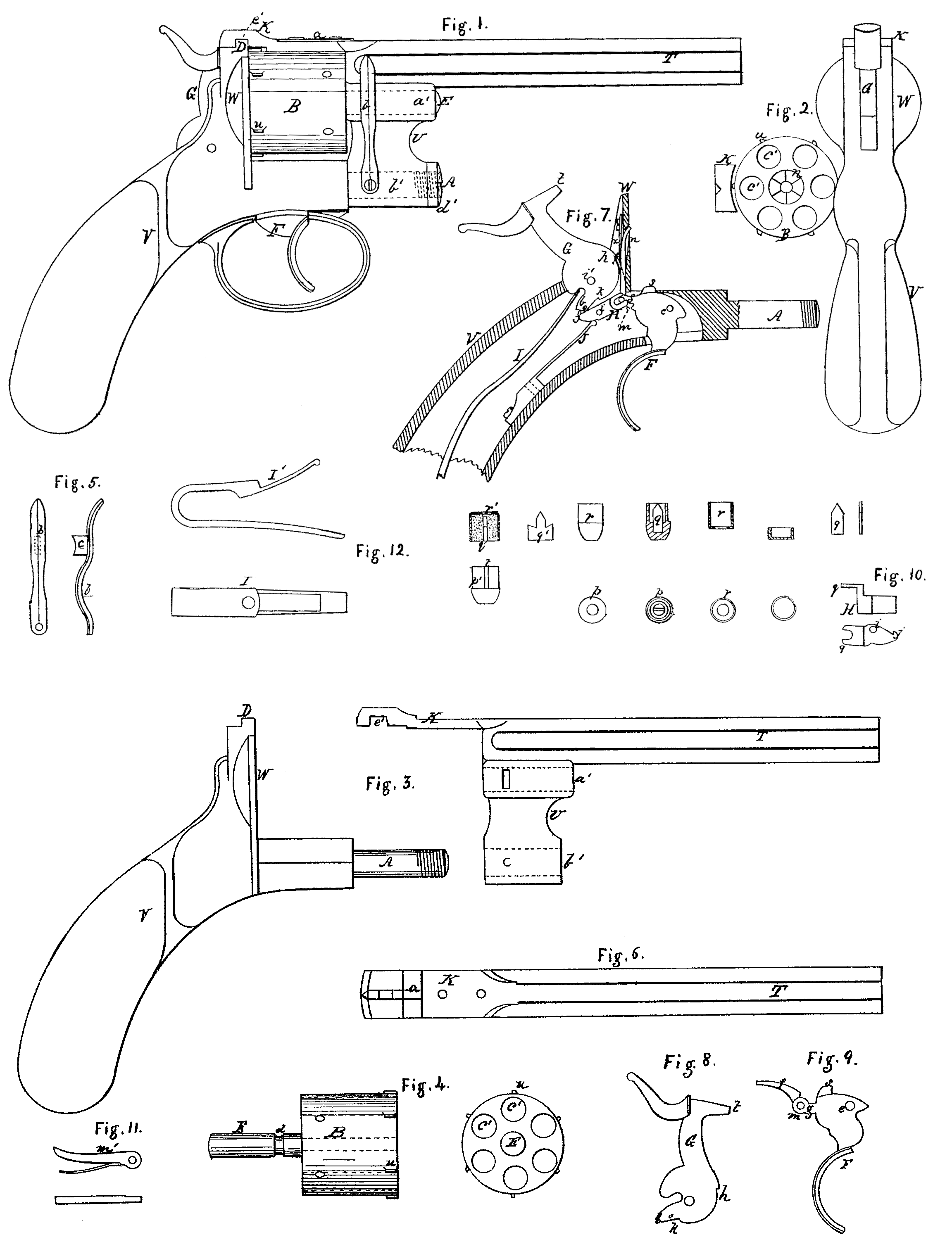
A side view of the pistol complete is shown in Figure 1, consisting of barrel, cylinder, breech-piece, and stock which contains the discharging mechanism.
The barrel T (shown in Figs. 3 and 6) is constructed with an arm, U, on its under side, bored at a’ and b’, for the reception of the cylinder and attachment to the stock V.
The cylinder B (shown in Figs. 2 and 4) has chambers c’ running entirely through, and is provided with a spindle, E, on its front end, which, passing through bore a’ of arm U, attaches it to the barrel and permits its rotation, a spring, b, Fig. 5, having a detent, c, which enters grooved of spindle E, preventing longitudinal movement of the cylinder after attachment.
Upon the stock is the breech-piece W, between which and the arm U the cylinder B rotates, and which constitutes the bottom of the several chambers c’ of the cylinder.
The barrel and the cylinder are attached to the stock by the spindle A upon the front extremity of the stock, passing through bore b’ of arm U, a nut, d’, preventing longitudinal movement, while the barrel and cylinder are free to move about the spindle A. A tailpiece, k, forms the rear prolongation of the barrel, having a notch, e’, passing over a projection, D, on the top of the breech-piece W, and provided with a spring-detent, a, which enters a notch in the head of said projection D and holds the barrel and cylinder in position for use. This construction permits the barrel and cylinder to be turned about spindle A until the cylinder clears the breech-piece, when the cartridges are inserted into the rear of chambers c’. Then the system is turned back until projection D enters notch e’ and the spring-detent a engages the notch in the head of said projection D. The pistol is then ready for use.
For the purpose of cleaning, the barrel is turned about spindle A, as above stated, spring b raised, and the cylinder withdrawn from its bearing a’.
Fig. 7 shows the interior of the stock.
G is the hammer, (seen detached at Fig. 8,) movable upon pin i’ and having a tendency to fall by the action of spring I. In its lower portion are the notches h, k, and l.
F is the trigger, (seen detached in Fig. 9,) turning upon a pin passing through e. Attached to its ear m by a pin, g, are arms m’ and f, the former moving outward through an opening in the breech-piece for rotating the cylinder by connection with ratchet n, and the latter, acting against the face of the hammer G below notch h, kept in position by spring x.
Between the ear m, trigger F, and tail o of hammer G is a lever, E. (Shown at Fig. 10.) This lever is movable upon a pin passing through i, and has its short arm acted upon by a spring, J, its portion g having a notch which embraces ping of trigger, so that the said lever is actuated by the movement of the trigger. The upper edge of the short arm has a notch, j, which is as will be hereinafter set forth.
The upper edge of the trigger. F has a projection, S, which projects, as shown in Fig. 7, when the piece is cocked, and, by reason of projections u on the cylinder, prevents the further rotation thereof.
Instead of the two separate springs I and J, there may be a single spring, as shown at I’, Fig. 12, acting on both hammer and lever H.
The point t of the hammer passes through an opening in the breech-piece and acts upon the peculiarly-constructed cartridge to effect the discharge of the load.
With the hammer G in the position of Fig. 1, if the trigger F be drawn back ear m will be elevated, arm f, acting under notch h, will cause the hammer to turn about pin it, while arm m’ moves upward and rotates the cylinder. The continued pressure on the trigger separates arm f from notch l, and permits the spring I to throw the hammer G into the position of Fig. 1, this continued movement depressing the short arm of lever H, so that notch j will not engage notch l. When the hammer falls the spring J restores the several parts to the position from which they started, and by pulling the trigger another chamber is brought into line with the barrel and the piece again discharged. If the thumb be applied to the hammer-head so as to draw it back, notch k will engage notch j and the point t rest in side of the breech-piece to permit the side revolution about spindle A for the purpose of loading, as described above. A continued movement of the hammer will effect the engagement of notches l and j, as shown in Fig. 7, the depression of short arm of lever H lifting ear in and causing arm m’ to act to rotate the cylinder, as before described, when the power was applied to the trigger F. When in this position the drawing of the trigger depresses the short arm of lever H, and, disengaging notches l and j, the hammer falls. This construction thus enables the hammer to be raised and the piece discharged by a continued pressure on the trigger, and at the same time admits of the piece being cocked previous to the time of discharge—an important point where close firing is desired, as the lifting of the hammer by the trigger is very likely to derange the aim.
I do not claim of itself extending the chambers through the cylinder, nor the attachment of the barrel to an exterior pin, A, separately considered; but
What I do claim as new and of my own invention, and desire to secure by Letters Patent, is—
Making the arm U between the barrel and exterior shaft the bearing for the cylinder by a shaft on the forward end of the cylinder passing through and secured to the arm, substantially as described, when the said parts are combined with breech-piece and stock, so that the cylinder is rotated and stopped and the discharge effected, substantially as hereinbefore set forth.
In testimony whereof I have hereunto signed my name before two subscribing witnesses.
E. CLAUDE.
Witnesses:
Geo. Patten,
W. S. Clary.