
US 28437
UNITED STATES PATENT OFFICE
A. J. GIBSON, OF WORCESTER, MASSACHUSETTS, ASSIGNOR TO HIMSELF,
JOHN BOYDEN, JOSEPH P. HALE, AND SAMUEL FISK, OF SAME PLACE.
IMPROVEMENT IN REVOLVING FIRE-ARMS.
Specification forming part of Letters Patent No. 28,437, dated May 22, 1860.
To all whom it may concern:
Be it known that I, A. J. Gibson, of Worcester, in the county of Worcester and State of Massachusetts, have invented certain new and useful Improvements in Breech-Loading Fire-Arms; and I do hereby declare that the following is a full, clear, and exact description of the same, reference being had to the accompanying drawings, forming a part of this specification, in which–
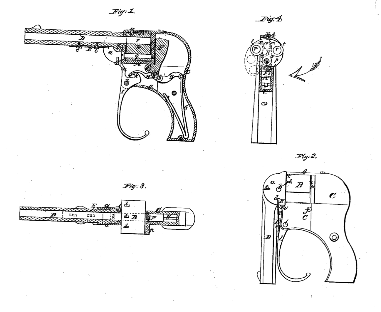
Figure 1 is a central longitudinal section of a pistol constructed according to my invention, representing it in condition for use. Fig. 2 is a side view of the same, representing it in condition for carrying in the pocket. Fig. 3 is a top view of the same, partly in section. Fig. 4 is a transverse section of the same.
Similar letters of reference indicate corresponding parts in the several figures.
These improvements are more especially designed for pocket-pistols, but are also applicable to other fire-arms.
The first improvement consists in a certain mode of combining the barrel with the stock or breech frame, whereby provision is made for moving the barrel, or a portion thereof, downward to a position at a right angle, or thereabout, to the position in which the firing is effected, for convenience of carrying the weapon in the pocket or of packing away in a small space, and for locking in either position.
A second improvement consists in combining the downwardly-movable barrel, or portion thereof, with a cocking and firing trigger or lever in such manner that it is rendered impossible to effect the discharge while the barrel is secured in its downward position.
To enable others skilled in the art to make and use my invention, I will proceed to describe its construction and operation.
A is an open-sided metal frame for containing the laterally-swinging breech-piece B. The back part of this frame constitutes the recoil-plate p, and the said frame is made in the same piece with a frame, C, which contains the lock and constitutes the principal portion of the stock.
a a are two parallel check-pieces, made in the same piece with or rigidly attached to the frame A, and projecting forward from the sides of the said frame to receive between them the barrel D, which is fitted snugly between them, and attached to them by a pivot, b, passing transversely through it below its bore and through the said check-pieces. Upon this pivot the barrel is capable of moving downward to the position shown in Fig. 2 viz., at a right angle to the position shown in Fig. 1 which is the position for firing. The front and lower edges of the check-pieces a a are finished off in the form of portions of corresponding circles described from the axis of the pivot b, and two notches, c and d, are formed in the edge of each of the said check-pieces viz., one, c, in front, and one, d, in the bottom.
E is a flat sliding bolt, attached to the under side of the barrel by screws e e passing through the said bolt and screwing into the barrel. When the barrel is in the position for firing, this bolt is capable of sliding into the notches c to lock it in that position, as shown in Fig. 1, and when the barrel is moved down to the position shown in Fig. 2 the said bolt is capable of sliding into the notches d d to lock it in that position. By drawing the bolt from the notches while the barrel is in either of the above positions it (the barrel) is left free to be moved to the other position.
F is the hammer, swinging on a pin, f, which passes through the frame C, and connected with the mainspring G by a stirrup, g, and a lever, H, the said lever being attached to the hammer behind and below the pin f by the pin h, which constitutes the fulcrum of the said lever, and the stirrup being connected by a pin, i, with the short rear arm of the said lever. The long front arm of the said lever is made with a hook, j, to catch on a hook, k, on the trigger or lever I, by which the hammer is raised and let off, and the mainspring acts upon the said lever in such a manner as to throw down the front arm of the said lever and its hook j, as well as to throw forward the head of the hammer. The lever I works on a pin, l passing through the frame C, and the downward pressure of the front arm of the lever H, acting on the hook k, tends to throw forward the lower part of the lever I, which hangs some distance below the frame C, as far as is permitted by an arm, m, of the said lever, which is drawn into contact with the front of the frame A. The back of the hook k on the lever I is made of cam shape, so that by drawing back the lower or trigger-like portion of said lever the said hook h, alter drawing forward the lever h and throwing back the hammer, is caused to throw up the front portion of the lever H, and so to raise `the hook j of the said lever clear of the said hook k and leave the hammer entirely under the influence of the mainspring, which throws forward its head and effects the firing of the charge. On the lever I being relieved of the backward pressure of the finger or hand the front arm of the lever H presses on the hook k and throws forward the lower trigger-like portion of the said lever H till the upper arm, m, of the said lever comes in contact with the front of the frame A. When the barrel is brought to the position shown in Fig. 2 the bolt E bears against the front of the arm, m, of the lever I, and on the barrel being locked by the entrance of the bolt E into the notches d the said arm is firmly locked between the bolt E and the front of the frame, and the lever I prevented being moved in any way, and therefore the hammer cannot he moved.
The head of the hammer is made with two horns, n n, which pass through openings in the recoil-plate. This construction is intended for the use of metallic cartridges having the priming in a hollow flange at its base, and the object of such construction is that the hammer may strike the cartridge at two points, so that though the priming may be defective at one point it may not fail to be exploded.
The breech-piece B is in the form of a portion of a cylinder, and contains three chambers, r r r, which are open at the rear. It is arranged to swing on a pin, q, which is parallel with the chambers, and is provided with notches t t t, one for each chamber, to receive a spring-catch, u, by which it may be locked with either chamber in line with the barrel. This form of breech-piece is not new; but it is so constructed with recesses s s in its sides, as shown in Fig. 4, and the bottom of the frame A is so constructed that it may swing so far out of the frame on one side, as shown in red outline in Fig. 4, as to permit the charging of all the chambers from one side of the stock, while such breech-pieces, as far as known to me, have been heretofore so constructed as to require one or more chambers to be charged at one side and the others at the other side of the frame A.
I do not claim broadly so constructing and applying the barrel of a fire-arm that it may swing downward on a pivot; but
What l claim as my invention, and desire to secure by Letters Patent,–
1. Combining the barrel with the breech frame or stock by means of a pivot, b, two doubly-notched check-pieces, a a, and a sliding bolt, E, the whole arranged and operating substantially as and for the purpose herein specified.
2. Combining the downwardly-movable barrel with the trigger or lever I or its equivalent in such manner that the said barrel may lock the said trigger or lever or its equivalent when it (the said barrel) is in its downward position to prevent the discharge, substantially as herein described.
A. J. GIBSON.
Witnesses:
Appleton Dadmun,
Silas D. Harrington.