
US 54065
UNITED STATES PATENT OFFICE.
J. B. DOOLITTLE, OF NEW HAVEN, ASSIGNOR TO HIMSELF AND GEO. O. DOWNING, OF HAMDEN, CONNECTICUT
IMPROVEMENT IN REVOLVING FIRE-ARMS.
Specification forming part of Letters Patent No. 54,065, dated April 17, 1836.
To all whom it may concern:
Be it known that I, J. B. Doolittle, of New Haven, in the county of New Haven and State of Connecticut, have invented a new and useful Improvement in Revolving Fire-Arms; and I do hereby declare the following, when taken in connection with the accompanying drawings and the letters of reference marked thereon, to be a full, clear, and exact description of the same, and which said drawings constitute part of this specification, and represent, in—
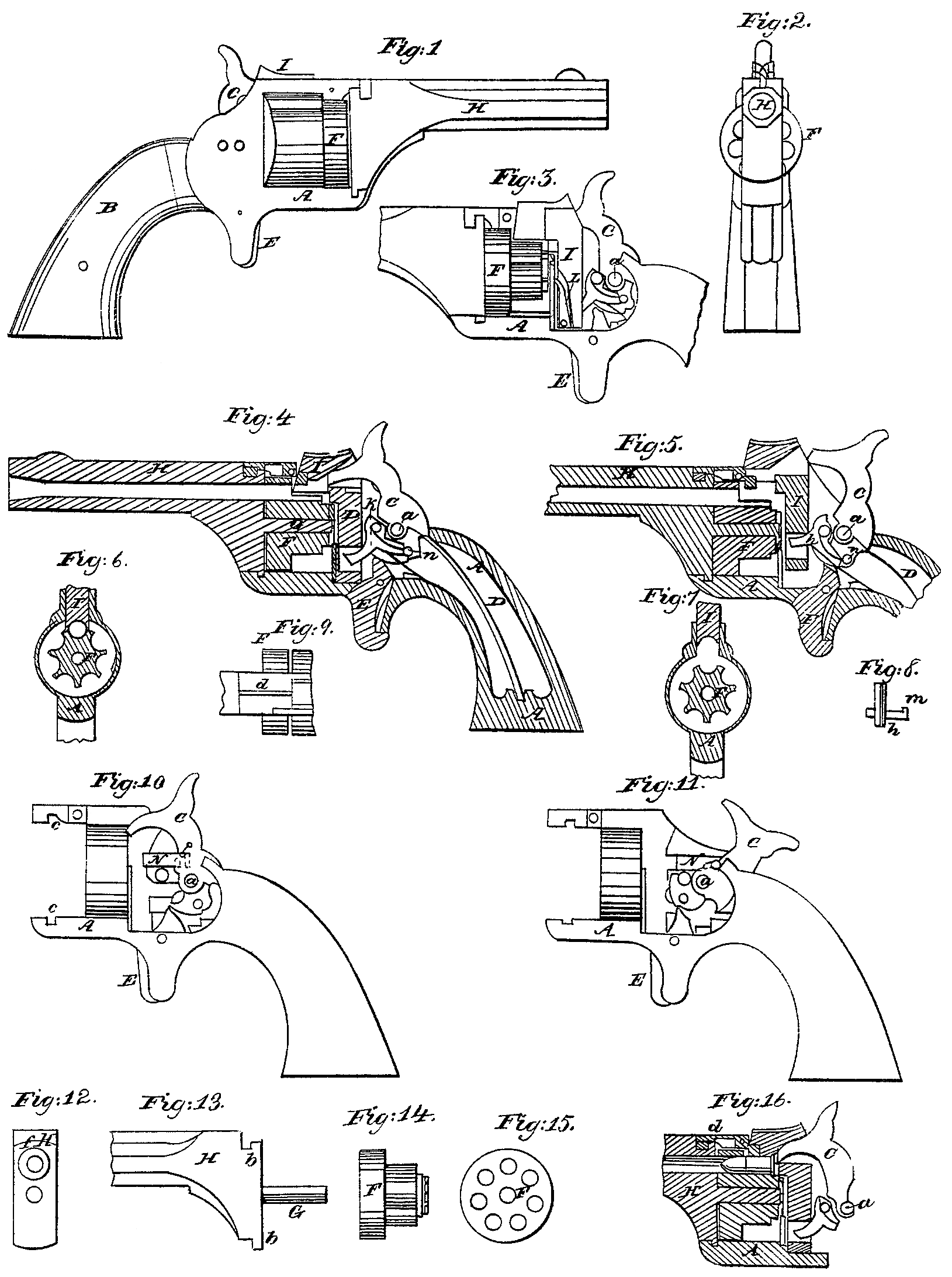
Figure 1, a side view; Fig. 2, a front or muzzle-end view; Fig. 3, a side view with the side plate removed; Fig. 4, a longitudinal section. Figs. 5 to 16, inclusive, illustrate the operation of my invention.
My invention relates to an improvement in that class of fire-arms which receive several metallic cartridges into a revolving cylinder, which said cylinder is caused to revolve by the act of cocking, to present successively each of the cartridges to the barrel for discharge; and it consists chiefly in the peculiar construction of the cylinder and the mechanism combined there with for operating the arm.
To enable others to construct and use my improvement, I will proceed to fully describe the same as illustrated in the accompanying drawings.
A is the frame, Within which is placed the operative parts, inclosed by a stock, B, in the usual manner. C is the hammer, pivoted at a ; D, the mainspring; E, the trigger, all constructed and operated in a common and well-known manner. F, the cylinder, differs from the cylinder as commonly constructed, in that, instead of having, the chambers entirely through the cylinder, the rear part of my cylinder, as seen in Fig. 14, is cut away, retaining only so much of the entire cylinder as will inclose the ball and just extend over the front end of the cartridge-shell, the front of the cylinder presenting the usual appearance, as seen in Fig.15, the rear being cut down to the center of the chamber, as seen in Fig. 6. The said cylinder is placed in the frame in the usual position, and is secured thereto by a pin, G, fixed to or made a part of the barrel H, the said barrel being provided with projection b above and below, as seen in Fig. 13, which lock into corresponding notches c, Fig. 10, said pin G passing centrally through the cylinder; and when the barrel is thus placed in the frame in the proper position a latch, d, (see Figs. 9 and 16.) catches into a notch, f, (see Fig. 12,) to hold it in its proper position.
I is a yoke, arranged to slide vertically with in the frame back of the cylinder, and extending over the cylinder so as to set down upon the cylinder and complete the chamber, which is in line with the barrel, as seen in Figs. 6 and 16. The said yoke is moved up and down by the operations of a lever, h, having its fulcrum at i, and acted upon by a pin, n, on the hammer, as seen in Figs. 4 and 5. As represented in Figs. 4 and 6, the yoke is down, forming a complete chamber. To raise the yoke, draw the hammer back, as seen in Fig. 5, the pin a bearing against the lever h, which extends into a mortise in the lower end of the yoke I, turns the lever, and raises the yoke, as seen in Fig. 5, and when sufficiently raised for the purpose hereinafter shown, the pin in passes over the end of the lever h and drops off back of a projection, m, (see Fig. 8,) and permits the yoke and lever h to return to the position seen in Figs. 4 and 6. To the said yoke I, I attach a pawl, L, which acts upon a ratchet on the rear of the cylinder to revolve the cylinder at each upward movement of the yoke.
When the yoke is down, to complete the chamber in Figs. 4 and 6 it is necessary to lock it in that position before the discharge takes place. For this purpose I place a slide, N, in the frame, as seen in Fig. 10, which is operated by a pin, P, on the hammer, so that when the hammer is drawn back, as from the position in Fig. 10 to that in Fig. 11, the slide also is drawn back, and when the hammer is returned the slide N will be forced forward and enter a notch in the yoke and securely hold the yoke down upon the cylinder.
To charge my arm, remove the barrel, turning it from the notches in the frame which secures it thereto, take the cylinder from the frame, insert the cartridges in the usual manner, return the cylinder and barrel to their respective places, and the arm is charged preparatory to firing; draw the hammer to full cock and release it in the usual manner. The hammer passes through a mortise in the yoke, striking the cartridge to discharge it in the usual manner. Then, for a second discharge, again draw back the hammer, in which operation the yoke I will be raised to permit the discharged shell to pass on and a new cartridge to be presented to the barrel, and in which operation the cylinder will be revolved to thus present the new cartridge, and when thus presented the yoke I will drop down onto the cartridge, thus forming a chamber around the cartridge; and in the return of the hammer the yoke will be locked in the manner before described, and the second cartridge discharged, and so on until all the cartridges have been discharged. Then remove the cylinder, eject the discharged shell from the cylinder, the pin G on the barrel being used for that purpose, place other cartridges in the cylinder, and operate as before.
The latch d, which holds the barrel in its position, extends at its rear end downward so as to rest upon the cartridge within the chamber, so that while a cartridge is in line with the barrel the barrel cannot be turned from its position, and will be thus held until the cylinder has made a partial movement so as to permit the latch to be raised from the notch in the barrel.
I do not broadly claim the yoke I in combination with a half-cylinder, as such is found in the patent granted to me July 29, 1862.
Having therefore thus fully described my invention, what I claim as new and useful, and desire to secure by Letters Patent, is—
1. The combination of a cylinder constructed with chambers complete for a portion of their length, and but half-chambers at the rear or remaining portion, with the yoke I, constructed and arranged so as to complete the chamber in line with the barrel, as and for the purpose specified.
2. The combination of the lever h with the yoke I and hammer, substantially as and for the purpose set forth.
3. The combination of the latch d with the barrel, when constructed and arranged so that the cartridge within the cylinder operates to lock the barrel in position, substantially as described.
J. B. DOOLITTLE.
Witnesses:
John E. Earle,
M. A. Hine.