US 33328
UNITED STATES PATENT OFFICE.
ETHAN ALLEN, OF WORCESTER, MASSACHUSETTS.
IMPROVEMENT IN REVOLVING FIRE-ARMS.
Specification forming part of Letters Patent No. 33,328, dated September 24, 1861.
To all whom it may concern:
Be it known that I, ETHAN ALLEN, of Worcester, in the county of Worcester, in the State of Massachusetts, have invented a new and Improved Mode of Constructing Revolving Fire Arms; and I do hereby declare that the following is a full and exact description thereof, reference being had to the accompanying drawings and letters marked thereon, in which—
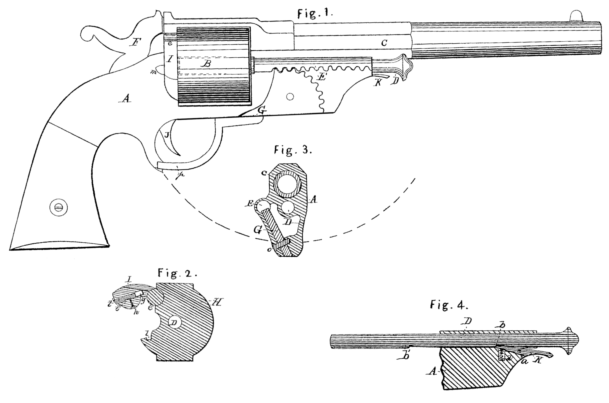
Figure 1 is an elevation of a revolving pistol with a portion of the shell or frame removed in front of the cylinder to show the arrangement of the gears, and Fig. 2 is a transverse sectional view through the recoil-plate; and Fig. 3 is a transverse sectional view, as indicated by the dotted lines in front of the cylinder. Fig. 4 is a longitudinal sectional view of the pin that holds the cylinder and a portion of the frame, showing the manner in which it is secured in place. Fig. 5 is an end view of the catch that secures the latch.
The nature of my invention consists in securing the cylinder-pin by a lever-catch.
To enable others skilled in the art to make and use my invention, I will proceed to describe its construction and operation.
A is the frame of a revolving pistol; B, the cylinder; D, the pin on which the cylinder revolves; E, the pin or rack which removes the cartridge-shell; F, the cock; G, the guard-lever; H, the recoil plate; I, the latch, and J the trigger.
This pistol (shown in the drawings) is designed to shoot metallic cartridges, and has six chambers within cylinder B, as in any ordinary weapon of this class. The cylinder B is adjusted in frame A and revolves on pin D. Pin D is secured in frame A by lever K, which is hung in frame A by pin a, and is pressed into recess b in pin D by spring d. When it is found necessary to remove pin D the thumb is pressed against the outer end of lever K, and at the same time against the head of pin D, and the pin is removed until spring d again presses lever K into recess b’, which is sufficient to allow the cylinder B to be removed. If it is desired to remove pin D entirely from frame A lever K is again pressed by the thumb, when it is entirely released.
The recoil-plate His provided with a latch, I, which is hung at e in the rear of cylinder B, and is secured by sliding bolt f, which is pressed outward by spring g, and is kept in place by screw h, in connection with recess i. When latch I is closed sliding bolt f is received into recess l, which secures it to recoil E. Bolt f is provided with a thumb-piece, m, which is pressed upward when it is desired to open latch I.
Guard-lever G is hung in frame A by pin o, and is provided with a segment of cogs, which play in corresponding teeth or cogs in pin E, while the opposite end forms the guard, as seen at p. It will be noticed that in order to have the pin E. come in range of all the chambers, and at the same time gear with guard-lever G, it is necessary to have the forward end or segment of guard-lever G form an angle of about sixty-five degrees with the base of the frame A, as seen in Fig. 3. The pin E is enlarged at one end, as seen at r, which is designed to fill the chamber of the cylinder B, and, in removing the cartridge, takes hold of the edges of the shell and ejects it with much less action of the pin than it would otherwise require.
The operation is as follows: The latch I is raised and the cartridge is put into the cylinder B through the opening, and the cylinder is turned by hand as each is filled until all the chambers are charged. The latch I is now closed, and the cartridges discharged by the ordinary method. The latch I is again raised, and the cylinder is turned by hand until one of the chambers comes in range with pin E, when guard-lever G is unhooked at p and is carried around to t, as indicated by dotted line, which carries the pin E through the cylinder and ejects the cartridge-shell, and the operation is repeated until all the shells are expelled, when the cylinder is charged as before.
Parts in this arm not mentioned are similar to those in common use. Therefore further explanation is not deemed necessary.
Having fully explained my invention, what I claim therein as new, and desire to secure by Letters Patent, is—
The lever, K, when applied to the extreme front of the frame A, so that the thumb will operate on it and the pin D at the same time, substantially as specified.
ETHAN ALLEN.
Witnesses:
Sullivan Forehand,
George W. Fairfield.

