
US 1149705
UNITED STATES PATENT OFFICE.
EUGENES. WARD, of PORTLAND, OREGON, ASSIGNOR. To OREGON ELECTRIC GUN Co., INCORPORATED, OF PORTLAND, OREGON.
SEARCHLGHT FOR FIREARMS.
1,149,705. Specification of Letters Patent. Patented Aug. 10, 1915.
Application filed March 6, 1913, Serial No. 752,325. Renewed December 10, 1914. Serial No. 876,557.
To all whom it may concern:
Beit known that I, Eugene Ward, a citizen of the United States, residing at Portland, in the county of Multnomah and State of Oregon, have invented certain new and useful Improvements in Search-Lights for Firearms, of which the following is a specification.
My invention has for its object to provide an attachment for firearms, in virtue of which the object to be sighted may be illuminated during the hours of darkness.
Generally, the invention provides a tubular body or light-barrel which is adapted to carry the lamp bulb and the lens, the light-barrel being secured beneath the revolver barrel by a connecting web which is detachably connected to the revolver barrel by a joint of the general dove-tail type.
Another object of the invention is to provide for readily adjusting the position of the lens toward or from the bulb whereby the focus of the light may be adjusted to suit the lamp used.
Again, it is the object to provide a circuit closing switch for the electric circuit operable upon cocking the hammer, and a latch device for holding the switch closed as long as desired, the switch being so arranged as to be automatically closable by the hammer and so arranged that it will remain closed until released by the user of the firearm.
My invention also provides a convenient means for connecting the wire terminal to the bulb socket and the bulb, whereby a rapid connection and disconnection may be attained when desired.
A further object of the invention is to provide a simple, efficient, neat and practical device of the character stated, that will, not detract from the utility or appearance of the firearm, or interfere in any way with the operation of the same.
More subordinately, the invention includes those novel details of construction, combination and arrangement of parts, all of which will be first fully described and then be specifically pointed out in the appended claims and illustrated in the accompanying drawings, in which :—
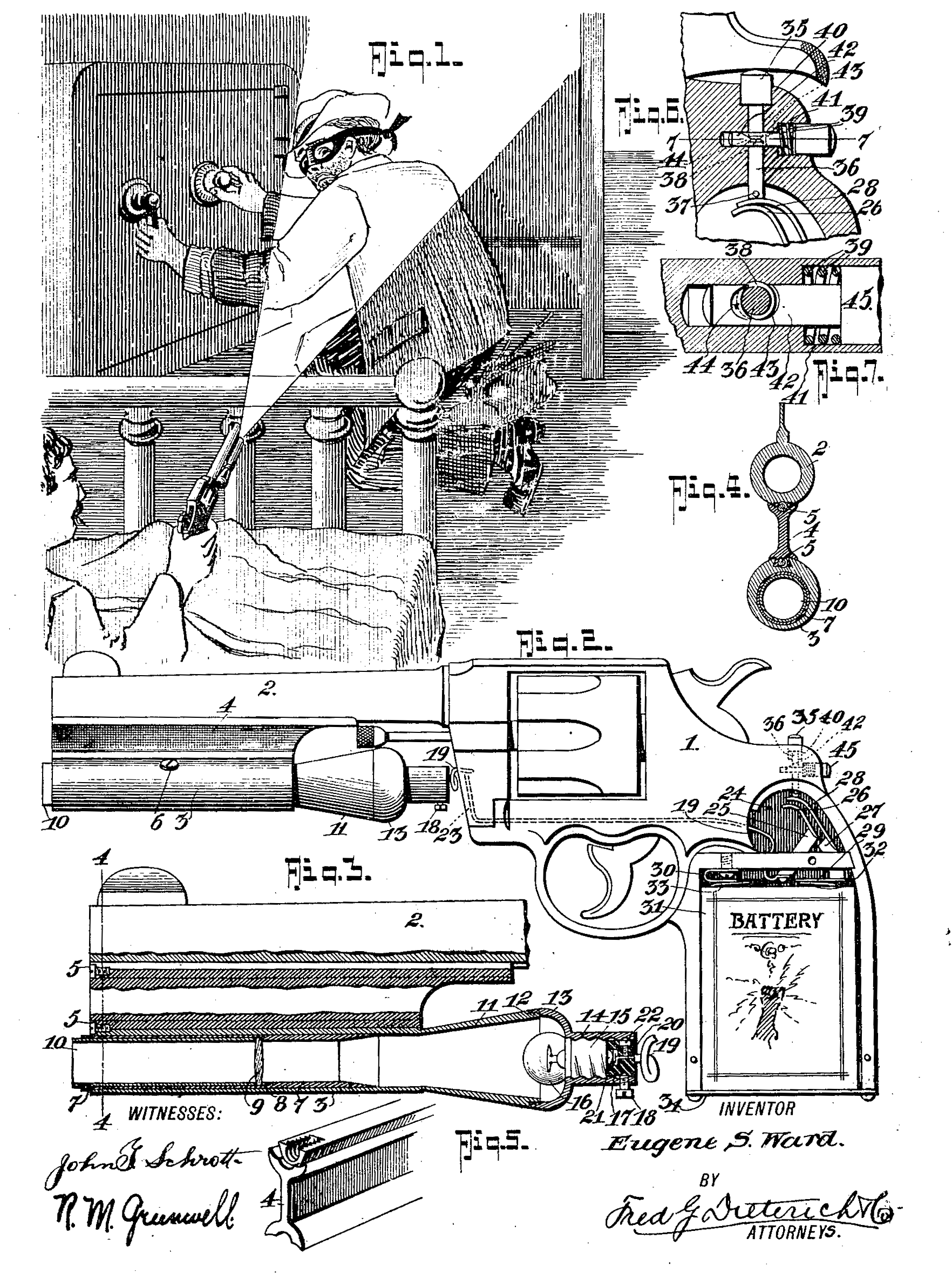
Figure 1 is a perspective view illustrating one of the uses of the invention. Fig. 2 is aside elevation of a firearm with the invention applied, one of the handle plates of the stock being removed. Fig. 3 is an enlarged section and part elevation of a portion of the same. Fig. 4 is a cross section on the line 4—4 of Fig. 3. Fig. 5 is a detail perspective view of a part of the connecting web between the two barrels. Fig. 6 is a detail section on an enlarged scale showing the circuit closing switch and its latch device. Fig. 7 is a horizontal section on the line 7—7 of Fig. 6.
In the drawings, 1 designates the firearm whose barrel 2 is provided with a dove-tail groove on its under surface to receive the upper dove-tail of a connecting web 4, the lower dove-tail of which fits into a corresponding dove-tail groove in the upper side of the light-barrel 3, set screws 5 being provided for retaining the web and barrels 2—3 in connection to prevent longitudinal displacement of the same.
Mounted within the light-barrel 3 is a tubular lens carrier 7, the same being adjustably held in place by a set screw 6. The carrier 7 has a shoulder 8 against which the lens 9 is held by a sleeve 10 which fits into the tubular carrier 7 with retaining friction, or if desired the tube 7 may be projected slightly, as indicated in Fig. 3, and provided with a set screw to hold the sleeve 10 in place.
The light-carrier tube 3 has an integrally formed rearwardly projecting bell cone 11 whose rear-end is threaded at 12 to receive the reflector cap 13, the latter being provided with a lamp base socket portion 14 into which the lamp base 15 is screwed. The lamp base 15, of course, carries the usual bulb 16.
17 is a block of insulating material, such as fiber, or the like, which slidably fits into the socket portion 14 and is held down by a set screw 18. The block 17 is bored to permit the end 20 of the wire 19 to project through and be headed as at 21 to form a contact terminal that engages the middle terminal of the lamp base. A set screw may be provided to engage the wire end 25 and hold it from movement,
The firearm stock is bored with a passage 23 through which the wire 19 passes and is concealed in the stock. The handle portion of the stock is hollowed out to receive the battery 31, which may be a multiple cell one, if desired, and the battery 31 has the usual terminals 32—33 that contact with the insulated terminal 29 and grounded terminal 30, respectively. The terminal 30 is electrically connected with the metallic parts of the wire terminal, while the terminal 29 is mounted on One of the handle plates 24 which is formed of insulating material. The contact 29 is an extension of the plate 27 which has one of the circuit closing resilient finger’s 28. 26 is a second resilient circuit closing finger carried by the plate 25, which latter plate is also mounted on the insulating handle plate 24 and to which plate 25 the wire 19 is connected.
34 is a closure plate or door for the handle chamber through which the battery 31 may be inserted or removed.
The contact fingers 28—26 are brought into contact to close the electric circuit by a push pin 36 which projects through a hole in the stock of the firearm frame and is held in place by the cross pin 37. The push pin 36 has a head 35 that fits in the counterbore 40 and is adapted to be engaged by the hammer of the firearm during the cocking act or to be manipulated by the finger of the operator, as desired. The push pin 36 when pushed down onto the finger 28 brings it into contact with the finger 26, the tendency of the finger 28 being to raise the pin 36 to hold the circuit open between the fingers 26—28. In order that the push pin 36 may be latched down to hold the fingers 26—28 in contact, I provide a latch device which consists of the latch pin 42 having a bore 43 through which the push pin 36 passes, the tubular pin 36 having a groove or indentation 38 to receive a projecting edge 44 of the latch pin 42. The latch pin 42 has a head 45 which operates in the counterbore 41 against the tension of a spring 39 which tends to hold the edge 44 in continuous contact with the push pin 36 so that when the push pin 36 is depressed, and the depression 38 comes into alinement with the edge 44, the latch pin 42 will latch the push pin 36 down in its circuit closing position.
The ball) base 15 having its outer terminal grounded to the metallic part 14, brings it into electric contact via the metallic parts of the firearm. with the contact 30. Thus when the circuit is closed between the fingers 26—28, the bulb 16 will be energized to generate the required light, which is focused by the lens 9 on the desired object.
In operation, the user’ may turn on the light by depressing the head 35 with his finger, before cocking the firearm and the light will remain oil until the operator pushes the head 45 to release the latch, or the operator may effect the lighting of the lamp by cocking the firearm, as indicated in Fig. 1 of the drawings.
From the foregoing, it will be observed that in my construction, the wire is practically entirely concealed in the stock of the firearm, and by providing the detachable block 17 it is only necessary to loosen up the upper screw 5 when the parts 4—3—11 and 14, etc., may be immediately detached from the barrel 2 as a unit. Thus, it will be observed that from my construction a neat appearing arrangement is provided that does not detract from the general appearance of the firearm.
From the foregoing description taken in connection with the accompanying drawings, it is thought the complete construction, Operation and advantages of my invention will be readily apparent to those skilled in the art to which it appertains.
What I claim is:
1. In combination with a firearm, of a light-barrel and a connecting web detachably dove-tailed into said barrel and also into the barrel of the firearm, said light-barrel having a conical extension at its rear end, a reflector cap detachably secured on the end of said extension and including a lamp socket, a bulb mounted in said socket, a lens carrier fitted for longitudinal adjustment in said light-barrel, means for holding said lens carrier in position, a source of current supply located in the handle portion of the stock, an electric connection between said Source and said bulb, said connection including a barrel block removably mounted in said socket, and a connecting wire running through a bore in the firearm to be concealed therein, and a circuit closing switch in said electric connection.
2. In combination with a firearm, a search-light and lens carrier mounted on the barrel of the firearm, a source of current supply within the handle portion of the stock, electric connections between said source and said searchlight and including a switch, said switch comprising a resilient contact finger,a push pin having a head adapted to be engaged by the hammer in cocking and having a pin to press said contact finger to its circuit closing position, and a finger releasable catch cooperating with said pin to hold the same to its circuit closing position when set.
3. In combination with a firearm, a search light and lens carrier mounted on the barrel of the firearm, a source of current supply within the handle portion of the stock, electric connections between said source and said searchlight and including a switch, said switch comprising a resilient contact finger, a push pin having a head adapted to be engaged by the hammer in cocking and having a pin to press said contact finger to its circuit closing position, a finger releasable catch cooperating with said pin to hold the sane to its circuit closing position when set, said catch comprising a latch. pin bored to permit passage of said circuit closer pin, said circuit closer’ pin having a depression and said lath pin having a projection to enter said depression when said circuit closer pin has been depressed to hold the same so, and a spring continuously tending to hold said latch pin in its latching position.
4. In a firearm, a light attachment including a lamp and a lens suitably mounted on the barrel of the firearm, a circuit wire leading from said lamp through and concealed in the body of the firearm, a battery concealed in the handle portion of the stock, a grounded contact in the frame of the firearm to cooperate with one of the battery terminals, a contact insulated from the frame of the firearm to contact with the other battery terminal, resilient circuit closing contact fingers concealed in the body of the firearm, one connected with said insulated contact and the other connected to said wire, a push pin having a head to be engaged by the hammer in cocking to bring said fingers into contact and close the electric circuit, means for holding said push pin in its circuit closing position, said means comprising a latch pin having a head to be finger-engaged, a spring holding said latch pin in its latching position, said latch pin having a projection to enter a groove in said circuit closing pin and retain said circuit closing pin in its circuit closing position until such latch pin is pushed by the finger of the operator to release the connection.
EUGENES. WARD.
Witnesses:
Fred G. Dieterich,
Albert E. Dieterich.