
British 13527
Specification of the Patent granted to Robert Adams, of
King William-street, in the City of London, Gun Maker,
for Improvements in Rifles arid other Fire-arms.—Sealed
February 24, 1851.—(Partly Communication.)
WITH AN ENGRAVING.
To all to whom these presents shall come, &c., &c.— The invention consists,
First, of improvements in the construction of rifle barrels of fire-arms;
Secondly, the invention consists of improvements in the construction of gun and pistol locks;
Thirdly, the invention consists of improvements in the construction and arrangement of safety-bolts or catches applied to fire-arms;
Fourthly, the invention consists of improvements in the construction of guns or other fire-arms arranged to load at the breech;
Fifthly, the invention consists of improvements in the construction of fire-arms, having only one fixed barrel with a series of loading chambers which revolve upon a centre, so as to bring each chamber alternately in a correct line with the barrel. And in order that the invention may be most fully understood and readily carried into effect, I will proceed to describe the means pursued by me.
The improvements in the construction of rifle barrels of
No. 1.—Vol. XIX.
fire-arms consist in forming raised ridges on the inner surface of such barrels in place of grooves or the ploughed hollows, commonly called “ rifling,” and I prefer to form such ridges angular, as shewn by the section of a barrel at fig. 1, but the shape and number of such ridges may be varied. My invention consists in forming raised or projecting spiral ridges on the interior surface of the barrels of fire-arms, a, a, are the projecting ridges, which are to be made in a spiral direction, similar to that heretofore resorted to for the grooves; £, b, are the grooves, which have a considerable extent of width as compared with the more narrow ridges heretofore: the hollows or grooves were narrow as compared with the projecting parts, and in fact, as heretofore constructed, the diameter of the bore of the barrel was taken across from the raised or internal projecting parts, the grooves being external of the measured diameter; according to my mode of construction the measured diameter of the bore of the barrel is from b to 5, the ridges being projected interiorly. I prefer to employ three such ridges at equal distances apart; but this, as before stated, may be varied; and the balls used with such barrels should be cast with notches or grooves to fit the barrels, and I have found that by such means no patches are required to be used with the balls.
Another improvement in the construction of the barrels of fire-arms consists in forming them near the breech with an internal hollow projection, which I prefer to be coned on the outside, as shewn at a, fig. 2, upon which the ball having a recess at one end corresponding in shape of the projection is placed. The passage or chamber from the end of the projection, a, to the priming, being of the proper dimension to receive the charge of powder suitable for such fire-arm; and the charge may be placed therein by inverting the barrel over the end of a tubular ram-rod into which the proper charge of powder has been first put, and then turning the barrel on end so as to discharge the contents of the ram-rod into the breech; or the ram-rod may be tubular, so as to allow the powder to be poured through it The ball is next rammed down on to the projection, a, thus effectually retaining the powder.
I will now describe the second part of the invention.
Fig. 3, shows front and back views of a bar or front-action lock, constructed according to this part of the invention; and Figs. 4, 5, 6, and 7, show several views of the parts of the lock separately.
This lock is composed of four separate parts only, and consists of a hammer or cock, a ; a plate, h ; a spring, c, and a screw, d. The cock, a, works on a pivot or axle, b\ attached to and forming part of the plate, b9 and through the pivot the screw passes, which holds the cock firm in its place, and also attaches the lock to the stock of the gun in the back-action lock, but in the bar lock by the usual tumbler pin or nut. The action of the lock is produced by the union of the main and sear springs in one piece, which spring at the end, c\ is provided with a semicircular piece in place of a tumbler, and the concave side of the part, c \ is notched or cut into notches to catch the tooth of a projecting sear; a1, fixed on to the inner side of the cock, a; the sear, a\ passing through the curved slotted opening, bl9 in the plate, b9 to take into the notched part, c , of the spring when the hammer is placed at half or whole cock; and the part, c\ has a stud, c\ which projects at right angles from it into the stock to be struck or
firessed by the action of the trigger to set the cock at iberty. The sear piece, a\ is rounded at its lower end, and traverses in the curved opening, b\ in the plate, b; when placing the hammer on half or whole cock, and the curved end of the opening, b\ limits the action of the cock in either direction. The stud, c3, fixed to and forming part of the spring, c, passes through the slotted opening, £>*, in the plate, b, and takes into a recess, a*, on the inner surface of the cock, and when the cock is pulled back, the recess, a\ acting on the stud, a3, compresses the spring. When the sear, a\ is released by the trigger depressing the stud, c\ a rapid motion will be given to the cock or hammer by the stud, c\
I will now describe the third part of my invention.
Fig. 8, shows a side view of apparatus, commonly called a safety-bolt or catch for bolting the cock or hammer, and preventing guns being discharged by accident Fig. 9, is a plan of the same parts; and Figs. 10 and 11, show a side view and plan of the hammer and cock-plate, with the safety-catch applied thereto.
On the circular part, a,-^T5f the cock or hammer are formed notches or ratchet-teeth, d9 into which the bent end of the lever or pall-bit, e9 takes and retains the hammer at half or whole cock, until released in the following manner: —The lever, e, is attached to and carried by a pin or axis, f which passes through the lock-plate into the bridle-leg; on the axis, f is fixed a second or inner sear, g9 the bent arm, g\ of which is lifted or depressed by the lever, A, carried by a projection, A1; on the inner surface of the trigger-plate, j9 is the grip-lever, one end being attached by a pin-joint to the projection, A1, the other resting on the end of the slot in the trigger-plate; i, is a spring, which is screwed to the inner surface of the trigger-plate, one end of the spring always pressing the arm of the lever, A, in contact with the lever, gl, upwards, so as to keep the lever-arm, c, in connexion with the ratchet-teeth on the hammer, the other end of the lever, A, resting upon the grip-lever, j9 which is constantly pressed outwards by the spring, i, the other end of the spring, i, acting on the trigger to keep it in position; the lever, A, has a spring, A*, affixed to it, as shewn, and when the grip-lever is pressed upwards the end of the spring, A2, depresses the arm, g\ and removes the lever, e, from the notches on the hammer when at half or full cock, but when the cock is resting or depending on the safety-catch any accidental blow or pressure on the grip-lever is received on the spring, A2, thereby preventing any injury or derangement of the safety apparatus, and prevents the lock being disengaged until placed at half or whole cock.
I will now describe the fourth part of the invention.
Fig. 12, shows part of a side view; and
Fig. 13, a plan of a gun arranged according to this part of the invention. Near the breech end of the barrel a mortice or opening is formed, through which the chamber or moveable breech turns horizontally upon a vertical axis. By this arrangement or construction the upper part of the barrel is continued along the upper part of the stock, and forms a plate to which it is affixed, and the metal at the breech is cut away, as shewn, to receive the moveable breech, the barrel being enlarged for that purpose, a, is the fixed part of the barrel of the gun, and A, the moveable breech turning with the pin, e9 to which the trigger-plate is attached, and is capable of turning at right angles with the gun, as shewn by red lines, so as to place the end of the moveable breech in a position to be loaded; d, is a bolt to retain the breech in a right line with the barrel when loaded.
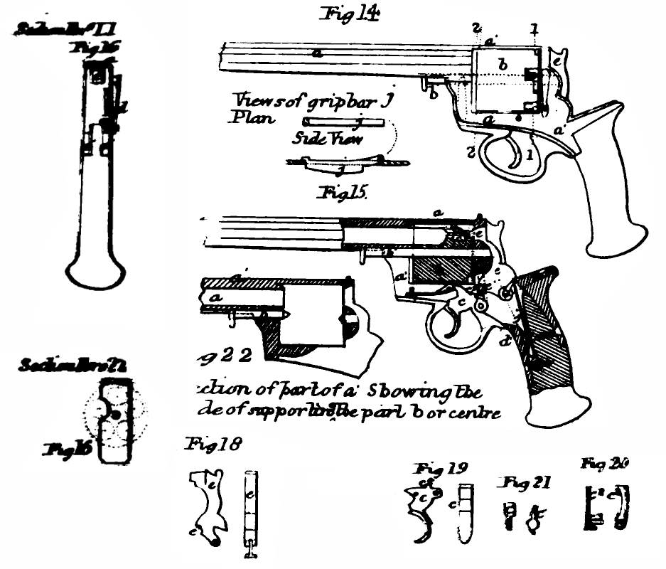
I will now describe the fifth part of the invention.
Fig. 14, shows a side view;
Fig. 15, a longitudinal section;
Fig. 16, a cross section;
Fig. 17, separate views of the revolving chambers; and
Figs. 18, 19, 20, and 21, show some of the parts separately of a gun or pistol having the improvements applied thereto, a, is the tube or barrel of any suitable length, and open at each end; the upper part being continued at a\ descends at right angles, returns, rises again, and joins the under side of the barrel, forming a rectangular opening, in which the series of chambers containing the several charges revolve, to be successively brought opposite to the barrel, a, and discharged, as hereinafter explained. The revolving chambers, 5, are supported by and revolve on the axis, bl, which slides in a groove on the under side of the barrel, through the rectangular frame, a, the end being supported in the back part of the frame, which is solid with the barrel, as shewn; and the series of revolving chambers may be readily detached from the opening through the frame by drawing the axis, b\ out towards the mouth of the barrel, or the series of revolving chambers may be supported on two conical centres, one or both of which may be capable of sliding out, so as to detach the series of chambers, as shewn in section at fig. 22. The back of each chamber is the recess, a, as shewn, to receive the nipple, b\ At the end are formed ratchet-teeth, b8, into which the perpendicular ratchet-lever, c8, (shewn in red lines,) works, the other end being connected to the trigger, c, by the pin, ca, which forms an axis for the sear, c\ which takes into a bent or recess, e\ formed in the front part of the cock or hammer, e; and when the trigger is pulled back, the sear, c\ lifts the hammer to a sufficient height for the action of the main spring to give it sufficient force to explode the cap; and the sear, c\ is thrown out of the recess, e\ by the projecting-nib or tooth on the cock, as shewn, when the cock is forced back to the fullest extent. The hammer strikes the cap in an horizontal direction, the striking part passing through a hole formed in the hinder part of the frame, a1; a spring-bolt, d, when pressed inwards comes against a shoulder on the hammer head, and retains it back to prevent the hammer discharging the cap by an accidental blow, or for safety in carrying, or when disengaging the part, b; f1 is a spring to return the trigger and parts attached to their original position; c\ is a stud on the trigger, which enters recesses on the outer circumference of the revolving chamber at the time each chamber is brought opposite to the barrel, a, and retains it there whilst the discharge takes place.
Having thus described the nature of the invention, and the manner of performing the same, I would have it understood that I make no claim to (he several mechanical parts separately, nor do I confine myself to the several details, so long as the peculiar character of any part of the invention be retained.
But what I claim is,
First, the constructing the interior of rifle barrels with ridges. I also claim the manufacture of barrels with internal projections for the powder to pass into and for the ball to fit on.
Secondly, I claim the improvements herein described in gun and pistol locks.
Thirdly, I claim the improvements herein described in safety-bolts or catches of fire-arms.
Fourthly, I claim the improvements herein described in guns and other fire-arms arranged to load at the breech; and,
Fifthly, I claim the mode of constructing the breech end of a barrel to receive a revolving series of chambers, and also the arrangement or combination of locks for such description of fire-arms.—In witness, &c.
Robert Adams.
Enrolled August 24, 1851.