
British 337
LETTERS PATENT to Thomas Restell, of New Kent Road, in the County of Surrey, Chronometer Maker, for the Invention of “ Improvements in Breech-loading and Revolving Fire-arms, and in Cartridges/’
Sealed the 29th July 1856, and dated the 8th February 1856.
PROVISIONAL SPECIFICATION left by the said Thomas Rested at the Office of the Commissioners of Patents, with his Petition, on the 8th February 1856.
I, Thomas Restell, of New Kent Road, in the County of Surrey, Chronometer Maker, do hereby declare the nature of the said Invention for “Improvements nr Breech-loading and Revolving Fire-arms, and in Cartridges,” to be as follows:—
My Invention relates to breech-loading and revolving or turning fire-arms, and consists in an improved trigger, together with the method of action thereof, which, by being drawn to and fro in a line parallel with the axial line of the barrel, releases the breech, brings the hammer back, brings the chamber containing the charge in position for being fired, brings into play a lever, which it holds at the back of and against the breech, (the lever forming a support thereto, and closing it air-tight,) and releases the hammer or apparatus which fires the charge; in an improved means of or apparatus for imparting rotary motion to a turning or revolving breech, actuated by the motion of the trigger; in a means of preventing any gases escaping between the chambers in the breech and the breech end of the barrel, by tapering off or decreasing the diameter of the extreme end of the breech of the barrel, placing thereon a packing of vulcanized india-rubber or other suitable material, which fits into a recess formed for its reception in the front of the revolving chambers; and in an improved form of hammer or apparatus for firing the charge, and method of propelling the same.
My improvements in cartridges consist in forming them of a tube of metal, burred down or otherwise fixed over the neck of a bullet, the ballet being cast with a shank, which is carried back inside the tube, and formed with a cup on the end thereof, for the reception of a charge of detonating powder, while the ordinary gunpowder is contained in the tube all round the shank of the bullet. The mouth of the tube is covered with a piece of water-proof and spark-proof paper, which I first prepare with sulphuric and nitric acid, in order that it may be entirely consumed, and leave no matter in the chamber to foul it; Qr the bullet and tube may be cast in one, with a metal shank, and the whole charged with detonating powder loosely, except at the end of the shank, where it is applied in the form of paste.
SPECIFICATION in pursuance of the conditions of the Letters Patent, filed by the said Thomas Restell in the Great Seal Patent Office on the 8 th August 1856.
TO ALL TO WHOM THESE PRESENTS SHALL COME, I, Thomas Rbstell, of New Kent Road, in the County of Surrey, Chronometer Maker, send greeting.
WHEREAS Her most Excellent Majesty Queen Victoria, by Her Letters Patent, bearing date the Eighth day of February, in the year of our Lord One thousand eight hundred and fifty-six, in the nineteenth year of Her reign, did, for Herselfc Hear heirs and successors, give and grant onto me, the said Thomas Restell, Her special licence that I, the said Thomas Restell, my executors, administrators, and assigns, or such others as I, the said Thomas Restell, my executors, administrators, and assigns, should at any time agree with, and no others, from time to time and at all times thereafter during the term therein expressed, should and lawfully might make, use, exercise, and vend, within the United Kingdom of Great Britain and Ireland, the Channel Islands, and Isle of Man, an Invention for “ ImproveKENTS IN BREECH-LOADING AND REVOLVING FlRE-ARK8, AND IN CARTRIDGES,” upon the condition (amongst others) that I, the said Thomas Restell, my executors or administrators, by an instrument in writing under my, or their, or one of their hands and seals, should particularly describe and ascertain the nature of the said Invention, and in what manner the same was to be performed, and cause the same to be filed in the Great Seal Patent Office within six calendar months next and immediately after the date of the said Letters Patent.
NOW KNOW YE, that I, the said Thomas Restell, do hereby declare the nature of my said Invention, and in what manner the same is to be performed, to be particularly described and ascertained in and by the following statement thereof, reference being had to the Drawings hereunto annexed, that is to say:—
My Invention relates, firstly, to revolving fire-arms which are loaded at tbe breech, and consists in an improved trigger, together with the method of action thereof, which, by being drawn to and fro in a line parallel with the axial line of the barrel, releases the breech, brings the hammer back, brings the chamber containing the charge in a position for being fired, brings into play a lever or tongue-piece, which it holds at the back of and against tbe breech, (the lever or tongue-piece forming a support thereto, and closing it airtight,) and releases the hammer or apparatus which fires the charge; in an improved means of or apparatus for imparting rotary motion to a turning or revolving breech, actuated by the motion of the trigger; in a means of preventing the escape of any gases between the chambers in the breech, and the breech end of the barrel, by tapering off or decreasing the diameter of the extreme breech end of the barrel, aud placing thereon a disc or packing of vulcanized india-rubber or other suitable material, which fits into a recess formed in the front of the revolving breech around the chambers; and in an improved form of hammer or apparatus for firing the charge, and a method of propelling the same.
My Invention relates, secondly, to cartridges, and consists in forming them of a tube of metal burred down, or otherwise fixed, over the neck of a bullet, the bullet being cast with a shank, which is carried back inside of the tube, and formed with a cup on the end thereof, for the reception of a charge of detonating powder, while the ordinary gunpowder is contained in the tube all round the shank of the bullet. The mouth of the tube is covered with a piece of water-proof and spark-proof paper, which I first prepare with sulphuric and nitric acid, in order that it may be entirely consumed, and leave no matter in the chamber to foul it; or the bullet and tube may be cast in one with a metal shank, and the whole charged with detonating powder loosely, except at the end of the shank, where it is applied in the form of paste.
The accompanying Drawings are designed to illustrate the several parts of tny Invention.
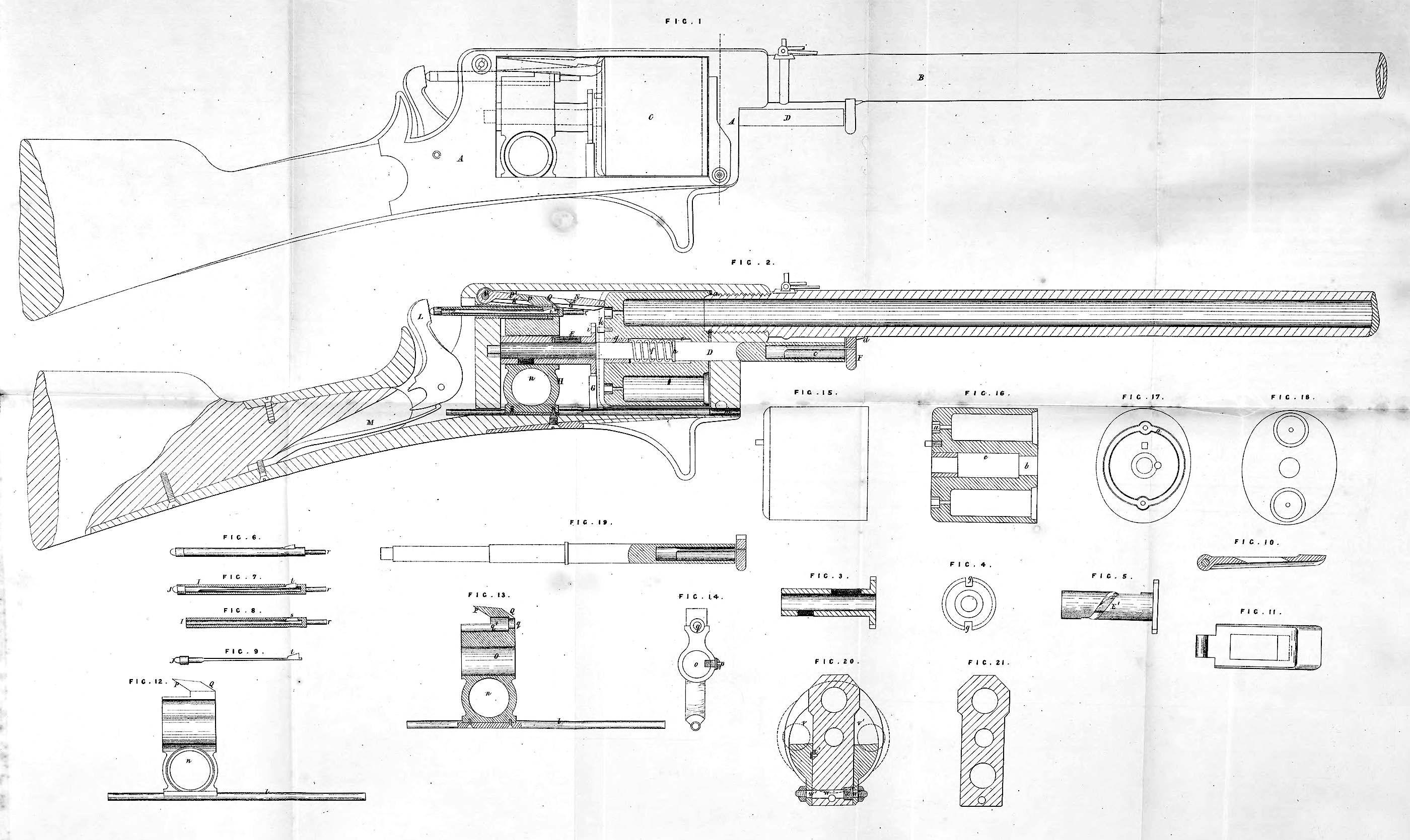
Figure 1 is a side view of a fowling-piece or rifle, in which are combined those parts of it which relate to fire-arms; and Figure 2 is a longitudinal vertical section of the same. The several portions of the gun are shewn in the positions they occupy when the discharge is on the point of taking place. A is the framework which contains the revolving breech and the greater part of the lock, together with the trigger and the apparatus for making the breech revolve, and for stopping it at the proper point, so that the proper charge chamber may be in a line with the barrel. B is the barrel, which is threaded on the outside at the breech end, and tapped into the front of the framework A, projecting a little within it, the projecting part being tapered off and receiving a disc of elastic material, which fits into the recesses a, in the front of the revolving breech around the chambers, to prevent the escape of gases when the discharge takes place. C is the revolving breech, which is pivoted and free to revolve upon the pin D, when necessary. This pin is passed through a hole in the front part of the frame A, the hole b in the centre of the revolving breech C and the tube E, and then enters into a hole in the back part of the frame A, and is kept in this position by means of a spring c and button F. The spring c is inserted and fixed in the end of the pin D, which is made hollow a sufficient distance in for the purpose, and the button F is rivetted or otherwise secured to this spring c, and is also cut away on the upper side next to the barrel, to correspond to the external form of the latter. A small inclined stop d is inserted into and projects from the under side of the barrel in front of the button F, which button, on the pin D being pushed in, passes up the incline of the stop d, and falls in behind it, thus holding the pin D in its place; when this pin D is to be removed, it is only necessary to pull the button F free of the stop d, and then withdraw the said pin. The hole in the breech C through which the pin D passes is recessed out or enlarged at e, so as to admit of a helical spring / being inserted between the pin and the breech. Part of the recess or enlarged portion of the hole is filled up by the steel ring or ferrule g, which is firmly secured in the back part of the breech. Between the ring or ferrule g, and the washer A, on the pin D, the spring f is placed, abutting against each, and forcing the breech C back along the pin D (when it is not otherwise held forward) so far as to carry it clear of the tapered end of the barrel B, and allow it to be turned round when necessary. The tube E, which is on the same pin D as the breech C, has a small projecting flange or disc i on its end next the breech C. The outer portion of this disc i is divided into two by the notches j,j, cut on its periphery, shewn more clearly in Figures 3 and 4; Figure 3 being a longitudinal section, and Figure 4 an end view, of the flanged tube E. The notches j, j, are of such a shape and size that a pin k, in the back of the breech C, will just fit into them, when the said breech is forced back by the helical spring /, as before described. The pin k is a little longer than the projecting tapered end of the barrel, so that it may partly enter one of the notches j before the recess a is entirely clear of the end of the barrel, thus preventing the breech from being moved round out of its proper position. One portion of the disc i, between the notches j, j, is made smaller than the other portion, and thus allows a stop. G to abut against the larger part of the disc t without coming in contact with the smaller. The tube E and disc i are thus free to make exactly half a revolution at each charge and discharge of the arm. I should here observe, that the half revolution is necessary in the case of the fire-arm I am now describing, because the number of charge chambers employed being two, the breech has to make half a revolution in removing one charge chamber from and presenting another to the barrel. Where the number of charge chambers is greater than two, the periphery of the disc i must be divided by a corresponding number of notches into a corresponding number of parts. In the tube E is cut a helical slot E1, shewn in Figure 5, which is a side view of the tube E. This slot E corresponds to half a revolution of the tube E, the disc t, and the breech C, and it is prolonged at each end in a direction parallel to the axis of the tube. The use of this slot El will be presently explained; H is the trigger, which is moved backward and forward within the framework A ; a rod or sliding wire l is screwed or otherwise secured to the lower part of this trigger, and slides in a groove or recess m in the framework A, to secure its parallelism. A hole n is formed in the trigger to receive the finger by which it is worked ; another hole o is formed in it at right angles to the hole n, and just above it, and in this hole o the tube E is supported, and partially revolves on the pin D; a pin p is screwed into the side of the trigger H, and projects on the inside, and takes into the helical slotE1, and by acting against the sides of this helical slot El, as the trigger C is pushed backwards and forwards, imparts a half revolution to the tube E and the disc i. This latter transmits its motion to the pin k, and through it to the breach C, whilst the disc i moves round in one direction, that is, when the trigger is drawn backwards; but when the trigger is pushed forwards, the pin & remains clear of the disc i, and therefore continues at rest. Above the hole o is formed in the trigger H another hole q, and recess q\ of. a size sufficient to admit the hammer or needle, and to allow it to move easily to and fro within it. The hammer or needle is formed in two parts I and J, of which a side view is seen in Figure 6, a section in Figure 7, and separate views in Figures 8 and 9 ; the tube I being in section in Figure 8. The outer part I is tubular to near the point or end r, which strikes the cap or j»ercussion mixture; a small slot * is cut through the tube I, so as to allow the catch t, which is formed on the end of the spring part J, and projects beyond the outer surface of the tube I, when at liberty to do so. A tube K, the inner dinmeter of which is sufficient to allow the hammer or needle to slide freely through it, is screwed into the back part of the frame A, and serves as a guide for the hammer. The rounded end of J abuts against the face of the cock L, which cock is projected or thrown forward by means of the main si>ring M, which takes into it The trigger H is cut away, or recessed at its upj>er part to within a short distance of its front in order to allow it to be drawn back along the tube K; before it is fully drawn back, however, the catch t of the hammer projects behind the trigger, and by it is caught and drawn back, until the inclined portion of the catch t comes in contact with the edge of the tube K, when it is gradually forced down and at last released, the hammer being immediately forced forward by the cock L and the main spring M. To force the breech forward against the tapered end of the barrel, and to prevent the recoil of the breech when the discharge is thus effected, a lever or tongue piece N, which is hinged or jointed to the frame A at 0, is drawn down by an inclined plane P, formed upon the top of the trigger piece which is prolonged for the purpose, this inclined plane P coming in contact with a corresponding inclined plane P1, formed on the lever or tongue piece N, and pulling it into the position shewn in Figures 1 and 2. By means of two : other inclines Q, Q1, the lever or tongue piece N is subsequently raised into the position shown by dotted lines, when the trigger H is pushed forwards, thus releasing the breech and allowing it to be forced back by the spring /, clear of the tapered end of the barrel, in order that it may be rotated. The lever or tongue piece N, with its inclines Pl, Ql, is shown separately in ! Figures 10 and 11, of which the former is a longitudinal section, and the latter a plan. The trigger H, with its sliding rod or wire lt its inclines P and Q, its holes m, o, and q, its recess q\ and its pin p, is shewn in Figures 12, 18, and 14; Figure 12 being a side view ; Figure 13, a longitudinal section; and Figure 14, an end view. t
Figures 15, 16, 17, and 18 are respectively a side view, a longitudinal section, a back end view, and a front end view of the revolving breech C, riu which are shown the hole b9 with its recessed or enlarged portion e, the steel ring or ferrule g, (with a screw g\ which secures it in its place,) the charge chambers (in Figure 18), the recesses a, a, the pin k, and a circular groove or channel a1, on the rear end of the breech, the object of which is to allow the breech to commence to rotate before the point of the hammer is withdrawn, through the whole thickness of the rear end of the breech, which is made much thicker than the sides to increase its strength.
Figure 19 is a side view of the pin D partly in section, shewing the relative sizes of its various parts, the washer h, the spring c, and the button F.
Figure 20 is a transverse section of the front part of the frame A, shewing an arrangement of flaps or covers for keeping the charges in the charge chambers after loading; for this purpose I employ two flaps v, v1, one on each side of the frame A. These flaps are carried on the square portions w\ w11, of the spindle u/, which turns in a hole in the frame A. A small helical spring x,. which presses at one end against the frame A, and at the other against the flap t/1, tends to keep the flap v close against the frame A, in which is fixed a small inclined catch or stud x1, behind which the flap v catches, (a notch being cut out of the flap for the purpose,) and by which it is kept closed. Since the flap v1 is fixed upon the same spindle as v, the former cannot open while the latter is closed, and therefore the one catch x1 serves to keep them both shut; y is a hole through which the end of the rod or wire l passes, when the trigger II is pushed quite forward ; this hole y is closed by the spindle w, when the flaps v and v1 are open, and therefore the rod or wire l cannot pass through it, but if pushed forward presses against the spindle w, in consequence of which the trigger itself is prevented from coming full forward while the breech is being charged, during which time it occupies the position indicated by the dotted lines in Figure 20.
In Figure 21, I have shewn a transverse section of the front part of a frame similar to A, in which I have formed a hole Z, through which a charge may be passed into one chamber, while the other remains in the position which it occupies when the piece is ready to be discharged.
Figure 22 is a side view of a musket for military purposes, in which six charge chambers are employed. This fire-arm so nearly resembles the fowling-piece already described, (except in respect to the number of its charge chambers,) that a detailed description of it will not be necessary ; I will, however, describe one or two modifications of the foregoing arrangements, which I have introduced into it. The first relates to the means by which the breech is caused to rotate. The modified apparatus used for this purpose is shewn in Figures 23, 24, and 25; Figure 23 being a side view of the tube aud disc, which correspond to the tube E and disc i in the fowling-piece; Figure 24, a view of the back side of the modified disc which I shall call i1, and Figure 25, a view of the front side of the same disc. In the present case, instead of forming a pin upon the breech to be acted upon by the disc as before, I employ a pin kl9 which passes through the disc t1, and takes successively into each of the recesses a11, in the rear end of the breech. These recesses a11 are shown in Figures 26 and 27, which are res|>ectively a back end view, and a longitudinal section of the revolving breech; Figure 28 being a front end view of the same. The pin kl is carried on one end of a curved spring Z1, the other end of which is secured to the disc i1 by the screw m\ The pin & is furnished with a knob or head n1, by which it may be taken hold of by the finger and thumb, and withdrawn from the breech in order to allow the latter to rotate. In Figures 24 and 25, Gl represents part of a stud or stop, corresponding to G in the fowling-piece, and the reduced portion of the disc t1 shewn above, and on either side of it corresponds to the reduced half of the disc t, of the fowling-piece. The reduced portion extends round the periphery of the disc, a less distance in this than in the former case, because of the increase in the number of the charge chambers, as has already been explained. The upper part of the disc i1 is cut away as shewn at o\ in order that the disc may not come in contact with the hammer.
Figure 29 is a transverse section of the front part of the frame of the musket, showing also an arrangement of parts for partially covering and for uncovering, as may be required, one of the six charge chambers or all of them successively. A1 is the frame; B1, a fixed plate, which prevents the charges behind it from falling out of their chambers; C1, a latch or guard piece which serves the same purpose as Bl, but on the other side of the frame A1. This piece C1 is centred upon a screw, and has below a short projecting portion c1, which is placed in a depression in the outer end of a horizontal piece D1, which is kept pressed out by a spring d\ that surrounds a stud formed upon the inner end of Dl, and bears against Dl at one end, and a screwed plug El at the other. By pressing the piece Dl inwards, the projection cl of C1 is carried inwards, and the upper end of C1 outwards, whereby the upper charge chamber on that side of the frame is uncovered aud may be readily charged. While this is done, the piece Dl, (and therefore C1 also,) may be retained in position by the rod or wire, which is attached to the lower part of the trigger, being pushed forward through both the hole e1 in the frame, and the hole f1, in the piece Dl, which are then in the same longitudinal line. By drawing the trigger back, the piece D1 will be released and pressed out by the spring d19 and the latch or guard piece Cl thereby thrown in front of the newly-charged chamber.
Figure 30 represents my improved cartridge. A2 is the tube, which is fixed over the neck a* of the bullet B3, which is formed with projections b*, which are designed to aid the bullet in taking into the grooves of a rifled barrel, when the piece with which it is used is discharged. C* is the shank which is cast in the bullet, and extends back within the tube A*, having formed on the end of it a cup c\ which receives the detonating powder, the ordinary gunpowder