
British 780
LETTERS PATENT to Joseph Bentley, of Liverpool, in the County of Lancaster, Gun Manufacturer, for the Invention of “Improvements in Breech-loading Fire-arms, and in the Cartridges to be used therewith.”
Sealed the 30th September 1856, and dated the 1st April 1856.
PROVISIONAL SPECIFICATION left by the said Joseph Bentley at the Office of the Commissioners of Patents, with his Petition, on the 1st April 1856.
I, Joseph Bentley, of Liverpool, in the County of Lancaster, Gun Manufacturer, do hereby declare the nature of the said Invention for “Improvements -in Breech-loading Fire-arms, and in the Cartridges to be used therewith,” to be as follows:—
This Invention consists in forming rifles, muskets, and other like small arms so that the barrel can be drawn or advanced from the breech in a direct line parallel to the bore of the barrel, for the purpose of allowing the cartridge to be inserted at the hinder end of the barrel; and in constructing the front of the breech of single-action fire-arms with a short cylindrical or truncated conical projection, so as to form a plug, which ships into the back of the barrel To insure a more perfect joint between the breech and the barrel; and an improved lock when applied to repeating fire-arms; also an improved cartridge Jo be used therewith.
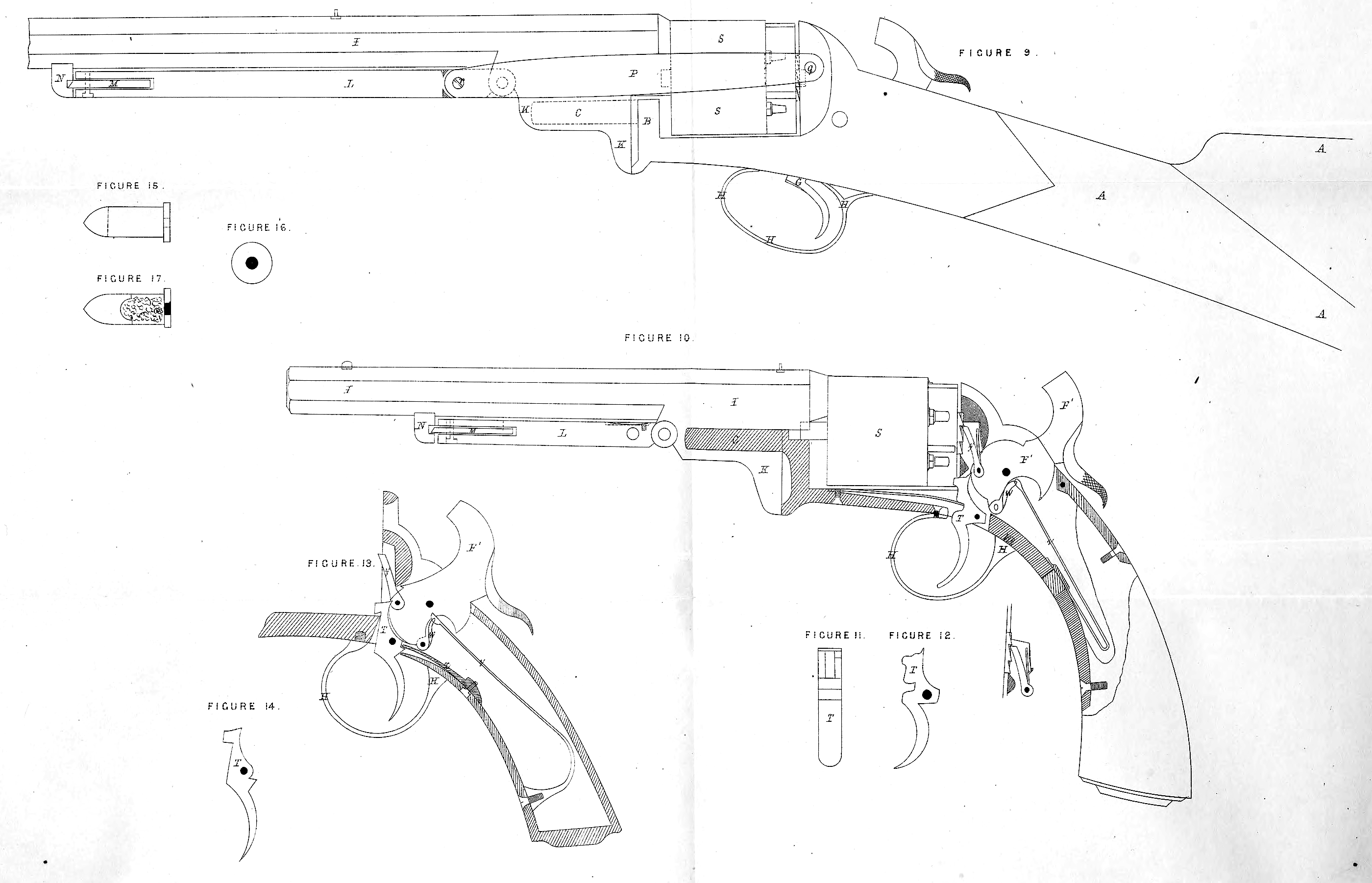
To accomplish these improvements the barrel is mounted, and works lered breech pistol partially in section, for the purpose of exhibiting my improved lock action. In this Figure the rotating chambers have their front bearing formed partly in the barrel foot, and partly in the stock frame; and Figures 11 and 12 are a front and side view of the trigger detached; Figure 13 is a sketch showing the mode I apply the trigger spring at the rear of the trigger; and Figure 14 is a side elevation of the trigger seen in Figure 13 shown detached; Figure 15 is a side elevation of my improved cartridge; Figure 16 is a back view of the same; and Figure 17 is a longitudinal section of ditto.
A, the stock; B, stock frame; C, a fixed spindle projecting forward from the stock frame, and upon which the barrel works longitudinally; D, a * truncated cylindrical projection upon which the barrel ships, and through which the passage from the nipple is formed; E, a small circular collar surrounding the vent from the nipple; F, the hammer; G, the trigger; H, the trigger guard; I, the barrel; K, the barrel “ foot ” which is bored for the reception of the 6pindle (C), upon which the barrel works longitudinally, and immediately in front of which is jointed L the working lever, which is fitted on its out end with M, a catch or bolt, which takes into a notch formed to receive it in; N, a small snug or projection on the under side of the barrel; 0, a small spring attached to the working lever, and which acts against the under side of the barrel when the lever is up, for the purpose of throwing the end of the lever into the palm of the hand of the operator, upon the catch on the end of the lever being relieved from the recess in the snug (N); P the side connecting rods, straps, or links which are jointed to the working lever at one end, and to the stock of frame at the other; q, a pin which passes through the lever, and attaches the two outer ends of the side straps (P) thereto; r, a pin which attaches the inner ends of the side rods (P) to the stock frame; S is a revolving-chambered breech, constructed with solid trunions or axles which rotated with the breech, the inner end working within a hole formed in the front of the stock frame, and the outer one revolves within a bearing formed in the hinder end of the “ foot ” of the barrel, or partly in the barrel and partly in the stock frame; F1, the hammer of my improved lock; T1, the trigger of my improved lock action; U, the main spring; W, the swivel or connecting link between the hammer and main spring; X, trigger spring; Y, a small lifter or pawl tooth, which is attached to the side of the lower limb of the hammer by a small pin, and is elevated or depressed by the motion of the hammer and being provided with a small spring at the back, and which presses against the back of the recess in which it works, causing the upper end of the lever to take into the ratchet formed on the back of the rotating chambers, and in its upward action forces them round.
Having now fully described and ascertained the nature of this my said Invention, and how the same may be carried into effect, what I claim is,—
Firstly, mounting the barrels of breech loading fire-arms upon a pin or spiudle (or pins or spindles) fixed and projecting forward from the breech, as herein-before described.
Secondly, the peculiar arrangement of side links and lever for causing the barrel to advance from and recede to the breech, as herein-before described.
Thirdly, the application of the spring to the working lever to cause it to spring from the barrel upon the locking bolt being withdrawn, and method of locking the liver.
Fourthly, the arrangement herein-before described for sliding the barrel of revolving breech-loading fire-arms backwards and forwards, for the purpose of inserting or taking out the revolving chambers.
Fifthly, arranging the “ bents ” on the face of the hammer, so that the “ trigger nose ” shall be advanced near enough to the chambers when at full cock, to cause the projecting stud on the face of the trigger head to act as a catch or bolt to the chambers, and also the forming of the trigger head with a vertical slot for the purpose of locking the chambers during the time of discharge, and until the trigger is relieved from the pressure of the finger, as herein-before described.
And lastly, the combination of the various parts herein-before described for constructing breech-loading fire-arms, substantially and in the manner herein-before described.
In witness thereof, I, the said Joseph Bentley, have hereunto set my hand and seal this Thirtieth day of September, in the year of our Lord One thousand eight hundred and fifty-six.
JOSEPH (l.s.) BENTLEY.
Witness,
William Walker.