
British 908
LETTERS PATENT to Alfred Vincent Newton, of the Office for Patents, 66, Chancery Lane, in the County of Middlesex, Mechanical Draughtsman, for the Invention of “Improvements in Fire-arms and Powder Flasks.”—A communication from Colonel Sam. Colt.
Sealed the 27th June 1856, and dated the 16th April 1856.
PROVISIONAL SPECIFICATION left by the said Alfred Vincent Newton at the Office of the Commissioners of Patents, with his Petition, on the 16th April 1856.
I, Alfred Vincent Newton, of the Office for Patents, 66, Chancery Lane, in the County of Middlesex, Mechanical Draughtsman, do hereby declare the nature of the said Invention for Improvements in Fire-arms and Powder Flasks, to be as follows:—
This Invention relates, firstly, to a novel mode of fitting adjustable sights to fire-arms, the object being to permit of the shifting of the sight without varying its position laterally. The sight is jointed to the gun in such a manner that it will be held in position by friction of contact, obtained by means of a binding screw. This binding screw may be caused either to operate upon a pair of conical socket pieces connected to the arm of the sight, or it may press down the fulcrum pin of the sight arm, and cause the fulcrum end of the sight arm to bear tightly against a concentric socket formed in the gun barrel to receive it.
When the binding screw is slackened the sight admits of ready adjustment, graduations being formed either on the bearing or the sight itself.
The Invention relates, secondly, to a mode of preventing the fonling of the barrels of fire-arms. For this purpose lubricating matter is applied to the barrel or chamber containing the charges from a reservoir provided with a piston or spring valve, for effecting or permitting of the discharge of the oil therefrom at certain intervals. The reservoir consists of a closed tube, which may be attached to a rotating breech fire-arm as an addition thereto, or it may constitute the rammer of the lever ramrod in the Colt fire-arm. It is fitted with a spring valve or plunger carried by a central rod, which when operated will force the valve from its seat, and open a vent for the discharge of oil into the ball beneath. When the rammer is the reservoir, the valve projecting from the end of the rammer will, when in use, come in contact with the ball, and be thereby forced back, so as to permit of the requisite discharge of lubricating material into the chamber containing the ball. The valve maybe opened either by the action of the lever ramrod or by hand.
The last part of the Invention relates to an improvement in flasks, whereby the amount of charge may be regulated as required. Between the body of the flask and the nozzle thereof is a sliding chamber for receiving the charge of powder and discharging it into the nozzle. The capacity of the chamber is regulated by an adjustable disc, which forms one end or side of the chamber. A coiled spring is employed for retaining the sliding parts which compose this chamber in the closed position, so as to prevent the escape of powder from the flask.
SPECIFICATION in pursuance of the conditions of the Letters Patent, filed by the said Alfred Vincent Newton in the Great Seal Patent Office on the 16th October 1856.
TO ALL TO WHOM THESE PRESENTS SHALL COME, I, Alfred Vincent Newton, of the Office for Patents, 66, Chancery Lane, in the County of Middlesex, Mechanical Draughtsman, send greeting.
WHEREAS Her most Excellent Majesty Queen Victoria, by Her Letters Patent, bearing date the Sixteenth day of April, in the year of our Lord One thousand eight hundred and fifty-six, in the nineteenth year of Her reign, did, for Herself, Her heirs and successors, give and grant unto me, the said Alfred Vincent Newton, Her special license that I, the said Alfred Vincent Newton, my executors, administrators, and assigns, or such others as I, the said Alfred Vincent Newton, my executors, administrators, and assigns, should at any time agree with, and no others, from time to time and at ail times thereafter during the term therein expressed, should and lawfully might make, use, exercise, and vend, within the United Kingdom of Great Britain and Ireland, the Channel Islands, and Isle of Man, an Invention for “ Improvements in Fuub-abms and Powdee Flasks,*’ being a communication from Colonel Samuel Colt, upon the condition (amongst others) that I, the said Alfred Vincent Newton, by an instrument in writing under my hand and seal, should particularly describe and ascertain the nature of the said Invention, and in what manner the same was to be performed, and cause the same to be filed in the Great Seal Patent Office within six calendar months next and immediately after the date of the said Letters Patent.
NOW KNOW YE, that I, the said Alfred Vincent Newton, do hereby declare the nature of the said Invention, and in what manner the same is to be performed, to be particularly described and ascertained in and by tbo following statement, reference being had to the Drawings hereunto annexed, and to the letters and figures marked thereon (that is to say):—
This Invention, as communicated to me by my foreign correspondent, relates, firstly, to improvements in adjustable sights for fire-arms.
As adjustable sights for fire-arms have been made heretofore, they are not only too costly, but the adjustment of them has been attended with serious difficulties. With the view to facilitate the adjustment, and to reduc3 the cost of sights for fire-arms, the Inventor proposes to make the sight at the extremity of an arm which is connected with the barrel by a turning or hinged friction joint, the friction thereof being capable of regulation by a temper screw without changing the position of the sight laterally. By this means the end of the arm in which the sight notch is formed can be elevated or depressed at pleasure to any angle to suit the required range, which angle is determined by an index, the friction being readily varied to admit of changing the elevation, and to insure the holding of the sight at any elevation desired.
In Sheet I. of the accompanying Drawings, Fig. 1 is a plan of the improved adjustable sight on the barrel; Fig. 2 is a longitudinal vertical section, Fig. 3 is a side elevation, and Fig. 4 a horizontal section thereof; Fig. 5 is a plan of a modification of the improved sight; Fig, 6 is a longitudinal section, Fig. 7 is a side elevation, and Fig. 8 a cross section thereof.
The same letters indicate like parts in Figures 1, 2, 3, and 4; in which Figures a, a, represent two lugs raised on the upper surface of the barrel and at a suitable distance apart, and these lugs have each a conical or tapering hole with the greatest diameter outside, and to these holes are fitted conical plugs 5, by so that they can turn therein with more or less friction, as may be determined, by the turning of a screw c, which passes through a central hole in one and is tapped into a central hole in the other. This screw also passes through a hub dy the ends of which are connected with the conical plugs by tongues ey e, so that the hub and plugs shall turn together. From the hub d a thin strip of metal or arm/, constituting the sight, projects forward, with the forward end turned up, as at <7, and with a notch h cut in the middle of the extreme end, through which to sight, in the usual manner. The upper edge of the lugs a, a, is concentric with the hub of the sight, and the face of one (or both) is graduated, as at iy to indicate the required elevation of the sight for various ranges, the arm / of the sight acting as the index hand or pointer. Now, it will be seen, that by turning the screw c in one direction the two conical plugs will be drawn towards each other, and into the conical holes, to which they are fitted, and that this will increase the friction, and render it more difficult to elevate or depress the sight, and vice versA In this way the friction which holds the sight, and which admits of adjusting it, can be regulated at pleasure by the mere turning of the screw without varying the position of the sight laterally^ a matter which it is important to observe. A modification of the mode of construction above described is represented in Figures 5, 6, 7, and 8, in which Figures the arm f of the sight is represented as made in the same form with the forward end turned up at gy and with a notch in the middle of the extreme end for sighting, as already described; but instead of the hub at the rear end, there are two sector wings k, k, one on each side, fitted to turn in recesses of corresponding form cut in the upper surface of the barrel. The upper edges of these wings are recessed to form cavities concentric with the curvature of the sectors to receive journal-like pins Z, Z, that project from the outer faces of two wings m, m, one on each side of the forward end of a plate n, which lies between the two sector wings &, k. The rear end of this plate n abuts against a shoulder© on the barrel, and when the pins or journals Z, Z, lie in their recesses in the sectors, and the sectors in their recesses in the barrel, the forward part of the under surface of the said plate is slightly elevated above the surface of the barrel so that by turning a screw y>, by which this plate is secured to the barrel, the journals can be drawn down into the recesses in the sectors, and the sectors in the recesses of the barrel; by this means the sight will be held firmly at any elevation to which it may be turned without the position of the sight being affected laterally. The face of one of the sectors can be graduated, as shown at qy the edge of the plate n acting as the pointer to indicate the elevation for any required range.
Although two forms of application of the Invention have been described, I do not wish to be understood as limiting my claim to such modes, as other modifications may be made without changing the principle thereof.
What I claim under the first head of the Invention is, making the sight for fire-arms at one end of an arm when the other end of the said arm is connected, substantially, in the manner described, with the barrel, by a turning or hinged friction joint, the friction of which can be regulated by a temper screw, substantially, as and for the purpose described, and without varying the position of the sight laterally.
The second part of this Invention relates to an improved method of preventing balls from fouling the barrels of rifles and other fire-arms, and facilitating the passage of the balls through the barrels on the discharge of the piece.
It is well known that the barrels of fire-arms, particularly those that are rifled, become fouled by the passage of the leaden balls through them in the act of firing, and that such fouling is of serious injury; and although many plans have been devised with the view to remedy this evil, I am not aware that any of them have been practically successful. The nature of this part of the Invention consists in applying lubricating matter in the barrels of fire-arms after the ball has been inserted, whether such lubricating matter bo applied to the outer surface of the ball or the inner surface of the barrel, by means of which the fouling of the barrel by the ball is effectually prevented, and the passage of the ball in the discharge greatly facilitated, while at the same time the lubricating matter will be prevented from reaching the charge of powder.
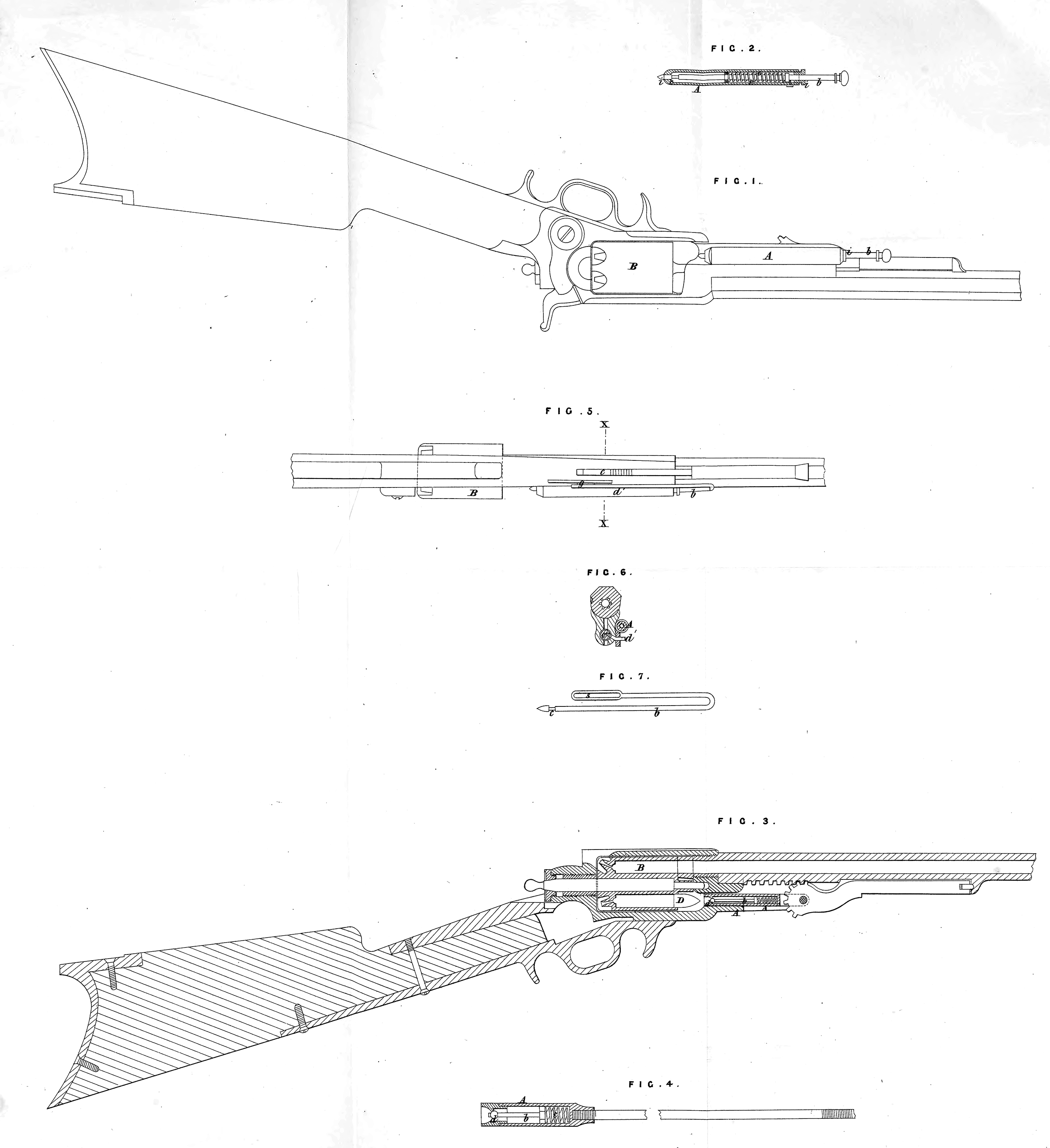
In Sheet II. of the accompanying Drawings, Fig. 1 represents the lubricator applied to a repeating rifle; Fig. 2 is a longitudinal section of the said lubricator; Fig. 3 is a longitudinal section of a rifle, with the lubricator applied to a “ Colt’s creeping fulcrum rammer;** Fig. 4 is a section of a rammer for muzzle-loading arms, with the lubricator applied thereto; Fig. 5 is an elevation of a repeating rifle, representing the lubricator as operated by the rammer; Fig. 6 is a cross section, taken at the line X, X, of Fig. 5; and Fig. 7 is a separate view of the stem of the lubricator.
The mode preferred of applying the improved method of lubrication to many-chambered rotary breech fire-arms is represented in Figures 1 and 2 of the accompanying Drawings, in which A is a small metal tube attached to the under part of the barrel and by the side of the rammer. The axis of the said tube is in a line with the bore of one of the chambers of the rotary breech B, w’hen another of the said chambers is in a line with the barrel. A cylindrical stem b is fitted to slide centrally in the said tube, and passes through a central hole in each end thereof. The outer end of this stem projects to a convenient distance beyond the outer end of the tube, and is there p:ovided with a head or button, for the convenience of pushing it towards the breech; it is surrounded by a helical spring e within the tube, by the tension of which the stem is drawn up to the position represented in the Drawings, but which admits of forcing the inner end down into the chamber that for the time being is in line. The inside of the tube is provided with suitable projecting guides to keep the stem in a true central position. The tube is charged with oil or other suitable liquid lubricating matter through a hole provided with a plug i. The surface of the stem b is recessed at c so far within the inner end, that when it is drawn up by the tension of the spring, the end beyond the recess closes the aperture at the inner or lower end of the tube to prevent the escape of the lubricating matter; but when the stem is forced down, or towards the breech, the passage of the recess by the aperture of the tube permits the lubricating matter to run out and hang by capillary attraction on the inner or lower end of the stem, which is then carried into one of the chambers of the breech, to deposit such lubricating matter thus discharged from the tube on to the outer surface of the ball in the chamber, where it runs and spreads over the entire surface of the ball so exposed. No more lubricating matter than is required can escape, because it is only during the passage of the recess that the escape can take place. That portion of the surface of the ball which is towards the muzzle being thus coated with oil, or other equivalent lubricating matter, as the ball is forced through the barrel by the discharge, the lubricated surface of the ball runs in contact with the bore, and thus effectually prevents the abrasion of the ball and the consequent fouling, and greatly reduces the friction of the ball as it passes through the barrel, while at the same time no portion of the lubricating matter can reach the charge of powder in the rear of the ball.
Instead of the mode of application above specified, the Inventor also proposes the application of the Invention to repeating fire-arms, having the many-chambered rotary breech, by forming the lubricating tube A in the rammer usually employed for driving or ramming the balls down in the chambers, as they are successively brought in line with the rammer by the rotation of the breech.
In this mode of application, the rammer is made tubular, with the head concave, to fit the surface of the ball D. The bottom of this cavity is pierced with a small hole, communicating with a tubular part A, which contains the lubricating matter. Within the tubular part there is a stem b, surrounded and acted upon by a helical spring c, which forces it downward, that its lower end, which is in the form of a valve, may close the aperture in the tube, to prevent the escape of the lubricating matter.
The extreme end of the stem at d projects within the concave recess of the rammer, so that, after the ball has been inserted in the chamber and brought under the rammer, in the act of forcing down the ball by the rammer the projecting part d of the stem comes in contact with the end of the ball, by which it is forced back to open the valve and permit the escape of the lubricating matter, which then spreads over the surface of the ball. The moment the rammer is lifted up, the tension of the spring forces the stem down to close the aperture, and prevent the further escape of lubricating matter. The rammer can be operated in the usual or any other convenient manner.
The same mode of application will answer for the rammers of muzzleloading fire-arms, as represented in Fig. 4, where like parts are indicated by the same letters as in Fig. 3.
Many-chambered rotary breech fire-arms may also be fitted with the lubricator by the side of the rammer, but the same being so connected with the rammer, that, by the act of ramming the ball in one chamber, the ball in the chamber next to it will be lubricated. This mode of application is represented in Figures 5, 6, and 7, of the accompanying Drawings, in which A represents the lubricator, constructed and located as in Figures 1 and 2, above described ; C, the usual rammer; B, the many-chambered rotary breech; and bt the stem, with its recess c; but the end of the stem, which projects outside of the lubricating tube, instead of being straight to be operated independently of the rammer, as in Figs. 1 and 2, is bent round the bent part, extending down parallel with the parts within the tube. The extreme outer end is slotted, as at s, to receive a pin &, which slides therein, and is attached to the rammers C, and works in a slot gf cut through the surrounding case of the rammer. By this arrangement, as the rammer is forced down to ram a ball in one chamber, the pin d1 at first slides in the slot s of the stem until it reaches the lower end of the said slot *, and then the continued movement of the rammer carries down the stem to lubricate the ball in the chamber corresponding therewith. As the rammer is drawn out, the pin i1 acts against the upper end of the slot 8, to restore the stem to its original position. In this mode of application no spring is required for restoring the stem to the required position in the lubricating tube.
It will be obvious from the foregoing, that many other changes may be made in the mode of application of the said Invention, such, for instance, as substituting a small pump or syringe for ejecting the lubricating substance, and that the lubricating substance instead of being applied to the ball may be applied to the inner surface of the barrel after the ball has been rammed home, as the object of the Invention is to lubricate the surfaces which act on each other as the ball is forced out of the barrel in the act of firing; and although I have only described the application of the Invention to the rammers of muzzle-loading fire-arms and to repeating fire-arms with the many-cliambered rotating breech, it will be obvious that it is equally applicable to other repeating arms and single-breech load arms; and it will also be obvious that motion may be imparted to the instrument which discharges the lubricating matter in various ways, although I prefer the mode above described.
What I claim under the second head of the Invention is, the method, substantially as herein described, of applying oil or other lubricating matter to the ball chamber or barrel after the ball has been introduced, by means of which the passage of the ball is greatly facilitated, and the fouling of the barrel is thereby prevented, as set forth.
The last part of this Invention relates to improvements in powder flasks for loading fire-arms, and consists in combining with the powder flask and ] charging nozzle thereof, and interposed between the two, a sliding chamber to contain a charge of powder, and which in one position communicates with the flask to receive the charge of powder, the communication with the nozzle being at the time cut off, and which by simply sliding the same will first cut off the communication with the inside of the flask, and then communicates with the nozzle to discharge the contents of the chamber.
And the Invention also consists in making one of the heads or partitions constituting the charging chamber of a flask having the features such as above specified in combination, adjustable to vary the size of charge.
These improvements in powder flasks are represented in Sheet III. of the accompanying Drawings, in which Fig. 1 is a vertical section of the flask; Fig. 2,a perspective view of the charging tube; and Figures 3 and 4, sections representing two modifications of the improved flask. A, Figures 1 and 2, represents a cylindrical tube secured to the lower end of a flask, and at right angles to its length. The nozzle a of the flask is attached to the opposite side of the tube A. One eud of this tube is closed and the other open, and two holes are made through its periphery on opposite sides, one D communicating with the inside of the flask, and the other c with the nozzle. To the inside of the tube A is fitted, so as to slide therein, a second cylinder tu.be B with open ends, but with a partition H inside to form one end of the charging chamber, the other end of the said chamber being formed by an adjustable stopper C, which can be moved at pleasure towards or from the partition II to regulate the capacity of the chamber to suit the required size of the charge. There are two holes cut through the tube B on opposite sides leading to the charging chamber, one F to communicate with the hole D leading to the inside of the flask, and the other E, when the tube B is in the required position, to communicate with the hole c leading to the nozzle. There is a pin g (represented by dotted lines) projecting within the cylinder A, and into a longitudinal slot s cut in the tube B, to limit the extent to which the tube B can be made to slide within the tube A, which sliding motion is given in one direction by a spring I, and in the other direction by the hand of the operator. The extent of motion (which is determined by the slot * and pin g) and the position of the several holes D, F and E, c, is such, that when the tube B is forced outward by the tension of the spring the charging chamber shall be in communication with and receive the charge of powder from the flask, and when pushed by the hand in the opposite direction, the communication between the charging chamber and the flask shall be first closed, and then the communication of the said chamber with the nozzle established to discharge the charge of powder from the nozzle. The outer surface of the tube B is ribbed, as represented at c\ Fig. 2, so that when sliding within the tube A, the amount of rubbing surface in contact with the inner surface of the tube A shall be very small, leaving cavities between the two surfaces, in which fine particles of powder will lodge, and thereby prevent the rubbing surfaces from fouling.
The improvements may also be applied in the form represented in Fig. 3, in which A and B represent two plungers or pistons on a sliding rod C at such distance apart as to form a chamber between of the required capacity to contain a charge of powder, the lower plunger being tapped or threaded on the stem of the rod C, so that it can be made to approach or recede from the plunger B to adjust the size of the chamber to vary the size of charge. The plungers are drawn up by the tension of a spiral spring within a tube D inside of the flask, and attached to the upper end thereof, one end of the said spring hearing against the inner end / of the tube, and the other against a shoulder on the head E of the rod. The plungers are fitted to slide in a cylindrical chamber K between the flask and its nozzle. When the rod and plungers are drawn up by the tension of the spring, the lower plunger A is in the cylindrical chamber, and the plunger B above it in the flask, so that the powder from the flask can run in to fill the space between the two plungers, which constitute the charging chamber; and as the rod and plungers are forced down by the hand of the operator, the plunger B first enters the cylindrical chamber to cut off the communication with the powder inside the flask, and then the plunger A passes out of the lower end of the said cylindrical chamber K into an enlargement L between it and the nozzle, to allow the charge of powder to be discharged through the nozzle. The upper part of the flask is provided with a stopper G for charging the flask with powder. The modification represented by Fig. 4 only differs from that represented in Fig. 3 in having the tube D extend down to the cylindrical chamber K at the bottom of the flask to form a continuation thereof for the plungers to work in, the said tube having apertures F, F, for the powder to pass from the flask into the charging chamber between the two plungers.
Although I have described and represented three modes of applying this part of the Invention, I do not wish to be understood as limiting myself to such forms of application, as they may be greatly varied by the substitution of equivalents.
What I claim under this head of the Invention is, combining with a powder flask and the nozzle thereof, and interposed between the two, a sliding chamber to contain a charge of powder, and moved in one direction by a spring, or the equivalent thereof, and in the opposite direction by the hand, the said sliding chamber being so constructed and located, substantially as described, that in one position it shall communicate with the inside of the flask to receive the powder therefrom, and in the opposite direction with the nozzle for the discharge thereof, and so that the communication with the one shall be closed before the other is opened, substantially as and for the purpose described.
And I also claim, under a combination such as above specified, making the capacity of the said charging chamber adjustable, in the manner and for the purpose substantially, as herein described.
In witness whereof, I, the said Alfred Vincent Newton, have hereunto set my hand and seal, the Sixteenth day of October, in the year of our Lord One thousand eight hundred and fifty-six.
A. V. NEWTON (l.s.)
Witness,
J. W. Moffatt,
66, Chancery Lane.