
US 82258
UNITED STATES PATENT OFFICE.
F. ALEXANDER THUER, OF EAST HARTFORD, ASSIGNOR TO COLTS FIRE-ARMS MANUFACTURING COMPANY, OF HARTFORD, CONNECTICUT.
IMPROVEMENT IN REVOLVING FIRE-ARMS.
Specification forming part of Letters Patent No. 82,2258, dated September 15, 1868,
To all whom it may concern:
Be it known that I, F. Alexander Thuer, of East Hartford, in the county of Hartford and State of Connecticut, have invented certain new and useful Improvements in Revolving Fire:Arms; and I do hereby declare the following to be a full, clear, and exact description of the same, reference being had to the accompanying drawings, and to the letters of reference marked thereon.
My invention relates to the kind of pistol or rifle which has a revolving chambered breech or cylinder capable of being loaded from the front, the principal object of the said invention being to produce a device by which a revolver adapted for the use of loose ammunition can at small cost be changed, so that cartridges having primed metallic shells may be used.
It has for a further object to provide, in a revolver, for the ejection at will of the cartridges or the empty cases from the chambers of the rotating breech, and also to provide against accidental discharge of the weapon.
To these ends my invention consists in placing a laterally-moving firing-pin holder between the hammer and the rotating chambered cylinder as a safety device.
It also consists in combining a rotating breech having chambers open at the rear and a laterally-movable plate located between the hammer and the breech and carrying an ejecting mechanism which is capable of being made to act by blows of the hammer; and my invention consists, lastly, in combining with a laterally-movable plate located behind the cylinder an ejecting mechanism and a firing-pin so arranged that either may at will be caused to act by blows of the hammer, substantially as hereinafter clearly set forth.
To enable others skilled in the art to make and use my invention, I will proceed to describe its application.
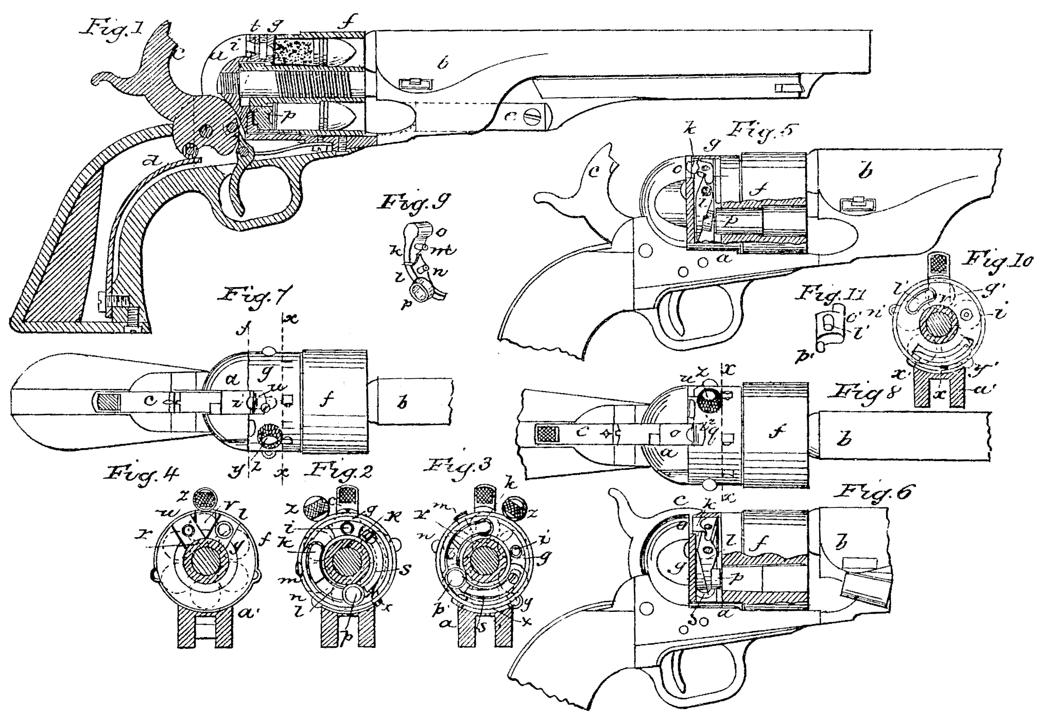
In the accompanying drawings, making part of this specification, Figure 1 shows a longitudinal section though the rear parts of a Colt’s revolver with my invention applied thereto. Fig. 2 is a transverse section at line X X, Fig. 7, showing the ring g in the proper position, to cause the ignition of a charge by the fall of the hammer. Fig. 3 is the same, but shows the ring g in the proper position to cause the ejecting mechanism to be struck by the hammer. Fig. 4 is a cross-section at line Y Y, Fig, looking forward, and showing the ring g turned into such a position that the hammer can strike neither the firing-pin nor the ejector. Figs. 5 and 6 are side views of the arm with the ring g in the same position as in Fig. 2, and with parts of the metal removed to show the contents of the ring and of one side chamber of the cylinder. Fig. 5 shows the condition of the parts when the hammer is at full-cock, and Fig. 6 shows their position after the hammer has fallen and an empty cartridge-case been thereby ejected from the chamber. Figs. 7 and 8 are plan views of the parts, showing respectively the ring g in the positions of Figs. 2 and 3; and Fig. 9 is a perspective view of the system of levers by which a blow of the hammer causes the ejection of a shell from a chamber not in line with the hammer.
Similar letters of reference denote the same part in the several figures.
In the above named figures, a represents the frame, b the barrel, e the hammer, d the main spring, and e the rammer, of a Colt’s pistol. These parts are in no manner changed from their usual forms and dimensions. The mechanism for rotating the cylinder f also remains unchanged.
f is the cylinder, which may be made by turning off the rear part of the original cylinder far enough to expose the ends of all the chambers, the part in the rear of these being reduced to the diameter of the ratchet r, which remains unchanged. This leaves a space be tween the original frame a and the ends of the chambers, which is nearly filled by a ring, g, which fits loosely around the reduced rear part of the cylinder f. Its outside diameter equals that of the chambered part of the cylinder.
The ring or annular plate g has in its face a deep annular groove, the ends of which nearly meet. Through the solid metal between the ends of the groove a hole is drilled, in which a firing-pin or punch, i, is contained. This firing pin reaches through the ring from front to rear, , and is of the proper length to transmit a blow of the hammer to the end of the cartridge, which lies in line with the hammer.
The annular groove in the ring g contains a system of two curved levers, k and l, the fulcra of which (about in the center of their length) are two screws, m and n, fixed in the ring. The first lever, k, has on its first end a prong, o, which passes backward through a hole in the back of the ring g. Its other end lies in front of the first end of the second lever, l, the other end of which is provided with an enlarged cylindrical protuberance or head, p, projecting forward about to the face of the ring g. A short extension of the lever l beyond p is pressed upon by a spring, s, which forces back this end of the lever l, and thus causes the prong o in the first end of the lever k to be protruded backward as far as possible. A recess, t, is cut in the back of the ring, at the place where the prong o protrudes, to give the face of the hammer access to the said prong. A similar notch, u, is cut in the back of the ring, where the firing-pin i cuts through, and another notch or recess, v, is made midway between t and u, for a purpose hereinafter explained.
x is a spring the free end of which projects beyond the periphery of the ring g. It serves, by catching over one or the other edge of the frame a,) in connection with the heads of the screws y and n, to hold the ring gin two different positions, (respectively shown by Figs, 3 and 2) A ball, z, projecting from the ring serves as a thumb-piece to move the ring about its axis into either of the positions represented in the drawings.
The centers of the firing-pin i, the prong o of the first lever, l, and the head p of the second lever, l, lie in a circle corresponding with the centers of the chambers in the cylinder, and the length of the levers is such that when the ring stands in the position of Fig. 3 the prong 0 is in line with the hammer and the head p of the lever l corresponds with the second chamber to the right. When the ring stands as in Fig. 2 the firing pin i lies in line with the hammer, and will transfer the blow of the hammer to the primer of the cartridge, which is in line with the barrel.
The operation of my invention is as follows: The chambers of the cylinder, which may be tapering, are loaded from the front with metal-cased cartridges in the same way as with the paper cartridges commonly used, the charges being rammed home with the rammer e. When it is desired to fire the charges the ring g is turned to the right by taking hold of the ball z, and the firing-pin is thus brought, in line with the hammer, as in Figs. 2, 1, and 7. The charges may then be successively fired in the usual way by cocking and snapping the hammer. After firing the charges the empty metallic cases or shells may be ejected by turning the ring g to the left into the position shown in Figs. 3, 5, 6, and 8, and then operating the hammer by cocking and snapping it as in the act of firing. The hammer now performs the additional functions of ejecting the shells by striking the prong o of the lever k, which causes the head p of the second lever, l, to start suddenly forward, and by thus giving a sharp blow to the end of each cartridge as they are successively brought into line with the said head the shells are forcibly ejected in a forward direction out of the chambers. (See Fig. 6.)
The chambers may be so shaped that the entire cartridges may be ejected without being fired.
The head p is shown, with a recess in its face, which permits it to strike only the edge of the cartridge, which, when these are of the center fire variety, avoids the danger of causing their explosion by the ejecting blow.
When it is desired to carry the pistol loaded the ring g may be turned into the position shown by Fig. 4. This brings the notch v into line with the hammer, which may be lowered so that its end enters the said notch and prevents the ring from turning. The firing-pin i is thus turned away from in front of the hammer and is left in a position where it is guarded by the frame from blows of any kind, while as there is no means of communicating blows of the hammer to the cartridges their accidental discharge is fully provided against.
I prefer to so proportion the chambers of the cylinder and the cartridges that the rear ends of the cartridges will protrude from the chambers far enough to permit the firing-pin and ejector to perform their functions without entering the chambers. This prevents the liability of the rotation of the cylinder being impeded if the pin or ejector should get out of order and tend to remain in their forward positions. The end of the firing-pin is blunt and rounded, so that it will be forced back by the ends of the cartridges when the cylinder is rotated. A thin extension of the periphery of the ring g hides the protruding ends of the shells.
Fig. 10 represents a modification of my invention applicable particularly to fire-chambered cylinders, Fig. 10 being a section corresponding with Fig. 3 and showing the ring g’ in the ejecting position. Fig.11 is a perspective view of the ejector l’. Accented letters of reference in these figures denote parts corresponding in function to those marked with the same letter in the other figures, i’ being the firing-pin, arranged and operating in the ring g’, the same as i in Fig. 3. l’ is the ejector, which, instead of being a lever, consists of a short segmental piece which slides in a perforation through the ring g’. This ejector is furnished with a prong, o’, on its rear end for the hammer c to strike against, and with a head, p’, at the forward end, which lies in line with the edge of the cartridge in the first chamber to the right of the hammer, looking forward. The ejector l is thrown bodily forward when struck by the hammer and transfers the blow to the end of the shell, which it ejects. The operation of this modification is the same as that of the one first described.
My invention is applicable to arms differing in construction from Colts. In cases where the frame extends over the top of the cylinder, as in Remington’s, the thumb-piece on the movable plate g will need to be located on one side instead of on top.
New arms may be made embodying my invention, in which it may be well to attach to the frame, between the hammer and the cylinder, a movable piece which shall perform the functions of the ring g— as, for example, a segmental piece capable of lateral movements around a hub concentric with the axis of the cylinder. This movable piece may be hidden in the substance of that part of the frame called the “recoil-shield,” and it may contain the firing-pin alone, or the ejector, or may bear both of these.
Having described several applications of my invention, I disclaim as new ejecting cartridge-cases by blows of the hammer, either director transmitted to shells in chambers not in line with the hammer. I also disclaim the use of a ring or plate at the rear of the chambers and containing the firing-pin, when the said plate is not movable in such a way that the firing-pin may be moved out of range with the hammer; but
What I claim as my invention, and desire to secure by Letters Patent of the United States, is—
1. The laterally-movable piece g, containing the firing-pin i, in combination with the rotating chambered breech and the hammer of a revolver, substantially as described, and for a safety device.
2. A laterally-movable plate, g, located between the hammer and cylinder of a revolver, and bearing the shell-ejector, substantially as and for the purpose hereinbefore set forth.
3. The combination of a movable piece supporting both the firing-pin and an ejector with the hammer of a revolver, and with a rotating breech having chambers open at the rear, when arranged to permit the use at will of the hammer, either as a means of igniting the charges or of expelling the empty shells from the chambers, substantially as hereinbefore specified.
In testimony whereof I have hereunto set my hand this 17th day of January, 1868.
E. ALEXANDER THUER.
In presence of—
C. B. Richards,
Horace Lord.