
US 99505
UNITED STATES PATENT OFFICE.
ROLLIN WHITE, OF LOWELL, MASSACHUSETTS.
IMPROVEMENT IN REVOLVING FIRE-ARMS.
Specification forming part of Letters Patent No. 99,505, dated February 1, 1870.
To all whom it may concern:
Be it known that I, ROLLIN WHITE, of Lowell, in the county of Middlesex and State of Massachusetts, have invented a new and useful Improvement in Revolving Fire-Arms; and I do hereby declare that the following is a full, clear, and exact description thereof, reference being had to the accompanying drawings, and to the letters of reference marked thereon, in which–
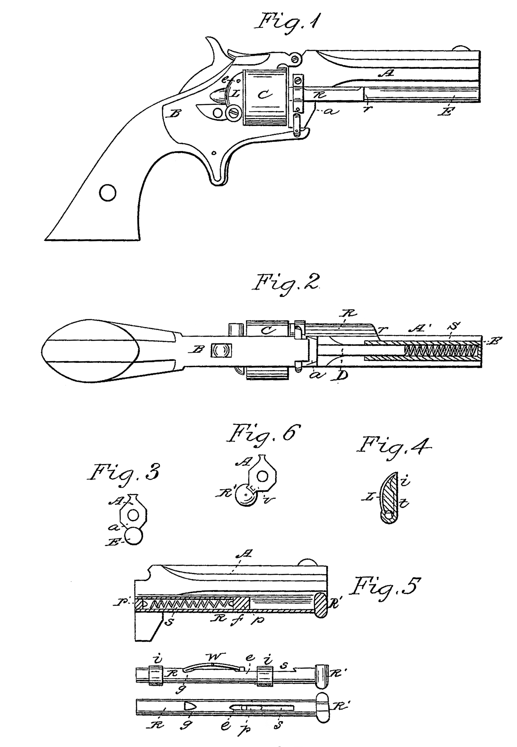
Figure 1 is a side view of a pistol containing my improvements. Fig. 2 is a view of the lower side of the same. Fig. 3 is a muzzle-end view of Fig. 1. Fig. 4 is a detached view of the gate and cartridge-guide L. Fig. 5 is a modification of my cartridge-ejector. Fig. 6 is a muzzle-end view of Fig. 5. Figs. 7 and 8 are views of another modification of my ejector.
My invention relates to that class of arms in which the revolving cylinder is bored clear through to form the cartridge-chambers, and in which the cartridge is inserted from the rear; and its object is to provide a convenient means of ejecting the exploded cartridge-shells, guiding the cartridges to their places, and securing them in their chambers in the cylinder.
I will now proceed to describe my invention as shown in Figs. 1, 2, 3, and 4 in the accompanying drawings.
A is the barrel, B the breech, and C the revolving cylinder.
R is the rammer or moving piston, which ejects the cartridge-shells.
D is a fixed piston lying under the barrel, parallel therewith, and firmly attached to the abutment a in front of the cylinder.
E is a hollow cylinder, closed at its front end, and having in its forward portion a spiral spring, S, The fixed piston D enters the rear open end of this cylinder, and the rammer R is rigidly connected with said cylinder E by a double elbow-joint, r. The sliding cylinder E is partially embedded in a segmental groove in the lower side of the barrel, as shown at o, Fig. 3, which prevents the said cylinder from being bent to the right or left by accidental blows.
L is a latch or gate pivoted to the breech in rear of the revolving cylinder to keep the cartridges in their places when turned up, as shown in black, Fig. 1, and which also serves as a guide for inserting the cartridges when turned down to the position shown in red lines. A spring, t, embedded in the face of this latch or gate, bears at its lower end against a squared or flattened side of the pivot on which it turns, and thereby operates to stop said latch or gate in its horizontal position, as shown by the red lines in Fig. 1.
A small beveled stud projecting slightly from the side of the breech at the point c (shown in red) fits into a recess, i, in the inner side of the latch or gate L and holds it in its upright position. This stud sits loosely in a socket in the breech, and its inner end bears against a spring. Consequently, when the latch or gate is raised from its horizontal position, as soon as it comes in contact with the beveled end of said stud a little additional force will press the stud inward, so that the said latch can pass till the stud comes opposite the recess i, when it will shootout into said recess and hold the latch in its upright position. When it is desired to turn the latch back to its horizontal position a little force will in like manner press the beveled stud inward, so that the latch will pass by it. When in its upright position this latch or gate prevents the cartridges from escaping from the cylinder rearward, and when turned down it stops as soon as its face comes in line with the chamber opposite to it, and so serves as a guide for inserting a cartridge. The breech or recoil shield in the rear of the cylinder and the abutment in front of it cover, or partially cover, all the chambers except the one which happens to be in line with the rammer R, so that when said latch or gate is turned up no cartridge can escape from its chamber forward or rearward. When the hammer is at half-cock one chamber is always in line with the rammer, and by pressing on the front end of the cylinder. E the rammer will be forced into the chamber, and will eject the cartridge or cartridge – shell therefrom rear. ward. The spiral spring S will retract the rammer from the chamber as soon as the pressure is removed from the cylinder E.
I will now proceed to describe the modifications of my invention shown in Figs. 5, 6, 7, and 8. In these figures, as in Figs. 1 and 2, A represents the barrel, and R the rammer or cartridge-ejector. R is a head on the outer end of the rammer R. In all these last-mentioned figures the rammer or ejector is straight, and is so attached to the barrel as to be directly in line with the chamber from which the cartridge is to be ejected, as shown in Fig. 6, thus obviating the necessity of any elbow.
The ejector shown in Fig. 5 operates on the same principle as that shown in Figs. 1 and 2, except that in the one case the spiral spring stretches out on pushing the rammer into the chamber and contracts by its own elasticity as soon as the pressure is removed, while in the other case the spring is contracted as the ram mer is pressed into the chamber and expands by its own elasticity as soon as the pressure is removed.
The rammer or ejector shown in Figs. 5, 7, and 8 is a cylindrical tube having in a portion of its length a slot, s, Figs. 7 and 8, and within it a piston, p, Figs. 5 and 8. The rear end of this tubular rammer is made solid by a plug, p’, and the spiral spring S is attached at one end to this plug and at the other to the piston p. Said piston p (in the modification shown in Fig. 5) is attached firmly to the barrel by a screw, f, which passes through the slot s in the tubular rammer, said slot being long enough to allow the requisite movement of the rammer sliding on the piston p, which remains stationary. On the side of the barrel is a dovetailed spline, v, which is embraced by a dovetailed recess in the head R’, as shown in Fig. 6. By this means while the head slides freely upon said spline it is held fast to the barrel and cannot be sprung away from it in any direction.
In the modification shown in Figs, 7 and 8 the piston p is not screwed fast to the barrel, but it has a small stud, e, projecting through the slot s, while a bow-spring, w, which is attached at its center to the barrel, with one end bearing in a notch, g, in the rammer and the other end against the said stud e of the piston p, prevents said piston from moving with the rammer when the latter is pushed back into the chamber of the revolving cylinder. The notch g in the rammer is so formed that as the rammer is pushed back the end of the spring will raise out of it on an incline, but when the rammer is again drawn forward the spring will be sure to enter said notch. In this modification it is necessary that the rammer be attached to the barrel by thimbles, as shown at i i, Fig. 7. By elevating the end of the spring w so as to disengage it from the notch g the whole rammer can be easily removed from the barrel.
It is manifest that the spiral spring S may be dispensed with, in which case the rammer will be withdrawn from the chamber by manual force.
In pistols of large size, to which the modifications shown in Figs. 5, 7, and 8 are best adapted, the spring to retract the rammer may be dispensed with with little or no detriment.
In all the modifications it will be observed that the part of the rammer which enters the chamber is free from any slot or other opening through which the burnt powder or other dirt can enter the interior to foul the spring or piston.
The spiral spring to retract the rammer may be on the outside of said rammer; but I prefer to inclose it in a tube, as shown in the drawings.
Having thus fully described the principle of my invention and the several modes in which I contemplate the application of that principle, what I claim as my invention, and desire to secure by Letters Patent, is
1. The combination of the fixed piston D, the hollow cylinder E, spring S, rammer R, and segmental groove in the barrel partially inclosing the cylinder E, substantially as described.
2. A cartridge-ejector with a coiled spring in closed in it for the purpose herein set forth, so constructed that there will be no slot or opening into the part that enters the chambers, substantially as and for the purpose set forth.
3. A support for the front end of the rammer or cartridge-ejector, substantially as herein represented and described, to prevent said front end from being bent or sprung by accidental knocks or blows.
4. The latch or gate L, in combination with a spring-stop to arrest and hold it in a horizontal position, as described, so that it will serve as a guide for inserting cartridges into the chambers of the revolving cylinder, as well as a gate to keep the cartridges in their chambers, as described.
ROLLIN WHITE.
Witnesses:
SAM. W. STICKNEY,
WM. U. AMSDEN.