
US 97780
UNITED STATES PATENT OFFICE.
FRANÇOIS ALEXANDRE LE MAT, OF NEW ORLEANS, LOUISIANA, ASSIGNOR TO CHARLES PIETRONI, OF LONDON, ENGLAND.
Letters Patent No. 97,780, dated December 14, 1869
IMPROVEMENT IN BREECH-LOADING REVOLVING FIRE-ARMS.
The Schedule referred to in these Letters Patent and making part of the same
To all whom it may concern:
Be it known that I, François Alexandre Le Mat, of New Orleans, parish of Orleans, and State of Louisiana, have invented certain new and useful Improvements in Revolving and Repeating Fire-Arms; and I hereby declare the following to be a full, clear, and exact description of the same, reference being had to the accompanying drawings, in which—
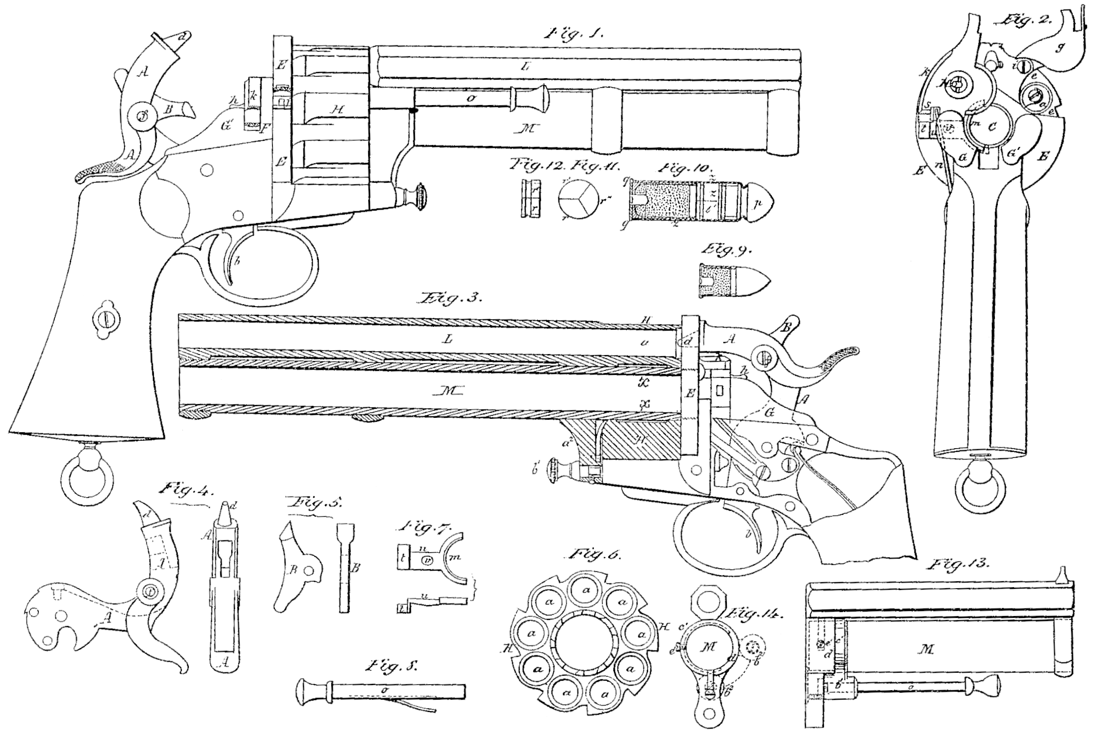
Figure 1 represents a side elevation of a fire-arm made in accordance with my invention.
Figure 2 is an end view of the same, with the hammer removed, so as to exhibit the revolving chamber and the breeches more clearly.
Figure 3 is a side elevation of the fire-arm, on the side opposite to that shown in fig. 1, the two barrels being represented in section.
The arm is composed of four distinct parts, viz: first, the cocking and discharging-mechanism, comprising the trigger-hammer, and other parts usually employed; second, the breech, which receives the mechanism especially intended to facilitate the loading; third, the revolving chamber; fourth the barrels.
Of the cocking and discharging-mechanism, the hammer differs from others commonly employed. It is composed of two hinged pieces. The one, A, which is the main part, is regulated directly by the trigger b, and carries at its end a percussion-pin, d, which acts on the ball-cartridge of the revolver. The other, B, is fitted in a recess in the part A, and can be turned upon a pivot or axis, f, and constitutes a beak or hammer, to strike the pin li of the piece k, which serves as the breech of the central barrel M, the arrangement of which, with relation to the other barrel L, is shown clearly in figs. 1 and 3, and will be presently described.
Figures 4 and 5 represent the two parts A and B separate.
The piece B is held in a slot in the part A, on the pivot f, and its upper end, which projects through A, constitutes a thumb-piece, by means of which it can be brought down in the position shown in fig. 1, so as to strike the percussion-pin h when the hammer falls. By drawing back the upper end, on the contrary, the hammer-part of the piece 3 will be drawn up in the recess formed on the under side of the part A (see fig. 4) so as to be out of the way, in which case, when the trigger is pulled, the percussion-pin k will not be struck, and the central barrel consequently will not be discharged. A spring located in the part A, as represented by the dotted line, fig. 4, and applied to the hub of the piece B, will retain the latter in either position.
The breech against which the evolving chambered piece H turns, is formed of a metallic disk, E, pierced with two cylindrical holes, C and D. The former, or central one, is intended for the central barrel M; the latter is located so as to come opposite the top chamber of the revolver, and is intended to allow the passage of the pin d of the hammer, so that it may strike the ball-cartridge.
On the circumference of the disk E is formed a recess for the introduction of the ball-cartridges.
After the revolving piece H is loaded, the recess is closed by a hinged piece, g, which fits it, and moves on an axis, i.
The spring j holds this piece in position.
The breech-piece k, of the central barrel, also moves upon a hinge. It carries the pin h, which, when struck by the piece B, is forced forward, as before explained, so as to produce the discharge of the central cartridge. This breech-piece is hinged so as to move laterally, as shown in fig. 2, and when pressed down, to close the central barrel, is tightly held in place between the stationary breech E and two strong metallic shoulders or projections, G G’, which are formed in one piece with the metallic part, which holds the trigger and mechanism connected with the same.
Whenever the hinged breech-piece is raised in order to load the central barrel, the cartridge-retractor m, which is a movable half cylinder, of the ordinary form employed for the purpose, and is arranged in the rear end of the central barrel in ally ordinary or suitable manner, throws out the cartridge-shell, and thus facilitates its removal.
The manner in which this is effected, is as follows:
In raising the breech-piece k, its heels presses obliquely against the rounded end t of the lever-arm u of the cartridge-retractor m, (see Figure 7.) which is capable of moving back and forth upon a stem or fixed axis, v. The half cylinder of the cartridge-retractor is thus caused to spring forcibly from the barrel, and to throw out the cartridge-shell.
A strong spring, n, maintains the hinged breech piece firmly in either its open or its closed position, and it is the action of this spring, in throwing back forcibly the hinged breech-piece, that causes the latter to strike the cartridge-retractor suddenly, so as to throw out the empty shell with considerable force.
The revolving cartridge-chamber H, which is shown detached, in Figure 6, turns upon the central barrel M, on which it fits with a slight fiction, and is provided with a circular recess, x, around the barrel, which will serve to hold the oil or other lubricator employed.
A small sliding rod, o, arranged in front of the piece H, in the usual manner, so as to be opposite the recess e in the stationary breech E, serves as a means to force out the empty shells from the chambers.
The upper and lower barrels L M are arranged parallel with each other. The former is used with the revolving chambered piece H, and is rifled to receive the ball-cartridge shown in Figure 8.
It is about the same length as the lower central barrel M, the interior of which is simply cylindrical, so as to receive the slug or shot-cartridge shown in Figure 10.
This cartridge is composed of a conical ball, p, on the neck of which is secured the front end of the cartridge-shell, which receives the fulminate and powder.
Between the two ends of the cartridge, I place a suitable number of slugs, r r’ r”, three in this instance, each constituting one-third of the cylindrical section of the cartridge, as seen in Figures 11 and 12.
The central barrel is screwed into the stationary breech E, and the upper barrel is held in place by means of two or more sleeves or collars, a^1 a^1.
The front sleeve, in this instance, is screw-threaded, as seen in fig. 2, and the rear sleeve has a downwardly-projecting part, a^2, which receives a set-screw, b^1, which is screwed into the stock or metallic portion connected therewith, so as to assure all parts in place. By loosening the set-screw, the upper barrel may be turned around the lower one, and unscrewed from it with ease.
It may be found desirable to so arrange the rod o that it can be turned under the central barrel when not in use. An arrangement for this purpose is shown in Figures 13 and 14.
The rod o slides in a socket, b^2, attached to a collar, c’, which fits on the neck d’, of the central barrel M.
A quarter-circle groove is formed in the collar c, which is traversed by the end of a screw, e’. This screw limits the movement of the collar, permitting it to be brought up to the position shown in red lines, fig. 14, in which position the rod o is ready for use, or to be turned down under the central barrel, as shown in fig. 13, which is the position occupied by the rod when its services are not required.
Having now described my invention, and the manner in which the same is or may be carried into effect,
What I claim, and desire to secure by Letters Patent, is—
1. The construction and arrangement with the central barrel, of its hinged breech-block, and the central firing-pin carried in the same, and located with relation to the hammer, substantially as described and shown.
2. The combination of the hinged breech of the central barrel, carrying the percussion-pin or firing-needle, as described, with the cartridge-retractor, under the arrangement and for operation as set forth.
3. The herein-described construction of the double hammer, with a permanent beak or pin for exploding the cartridge of the revolver, and a hinged auxiliary hammer, constructed and arranged substantially as specified, to strike against the percussion-pin of the central barrel.
In testimony whereof, I have signed my name to this specification, before two subscribing witnesses.
F. A. LE MAT.
Witnesses:
G. Lafond,
F. Olcott.