
US 535097
UNITED STATES PATENT OFFICE.
FRANK B. FELTON, OF HARTFORD, CONNECTICUT, ASSIGNOR TO THE COLT’S
PATENT FIRE ARMS MANUFACTURING COMPANY, OF SAME PLACE.
SAFETY DEVICE FOR REVOLVERS.
SPECIFICATION forming part of Letters Patent No. 535,097, dated March 5, 1895.
Application filed March 27, 1894. Serial No. 505,297. (No model.)
To all whom it may concern:
Be it known that I, FRANK B. FELTON, a citizen of the United States, residing at Hartford, in the county of Hartford and State of Connecticut, have invented a new and useful Improvement in Revolvers, of which the following is a specification.
My Invention relates to an improvement in that class of revolvers in which the cylinder is journaled upon a crane arranged upon an axis below the cylinder and parallel with the axis of the cylinder, so that the crane and the cylinder may be turned laterally outward from the frame, for loading, or for the ejection of shells.
The object of my invention is to provide such a connection between the cylinder and the lock or firing mechanism, that the crane and cylinder cannot be turned laterally out of their normal position in the frame, while the lock is cocked, that is in the firing position, and that should the lock be cocked, when the crane and cylinder have been turned out of the frame, these cannot be returned to their normal position until the lock has been uncocked or brought to its position of rest.
In the accompanying drawings, forming a part hereof, I have illustrated a mechanism by which this object may be attained, in which drawings—
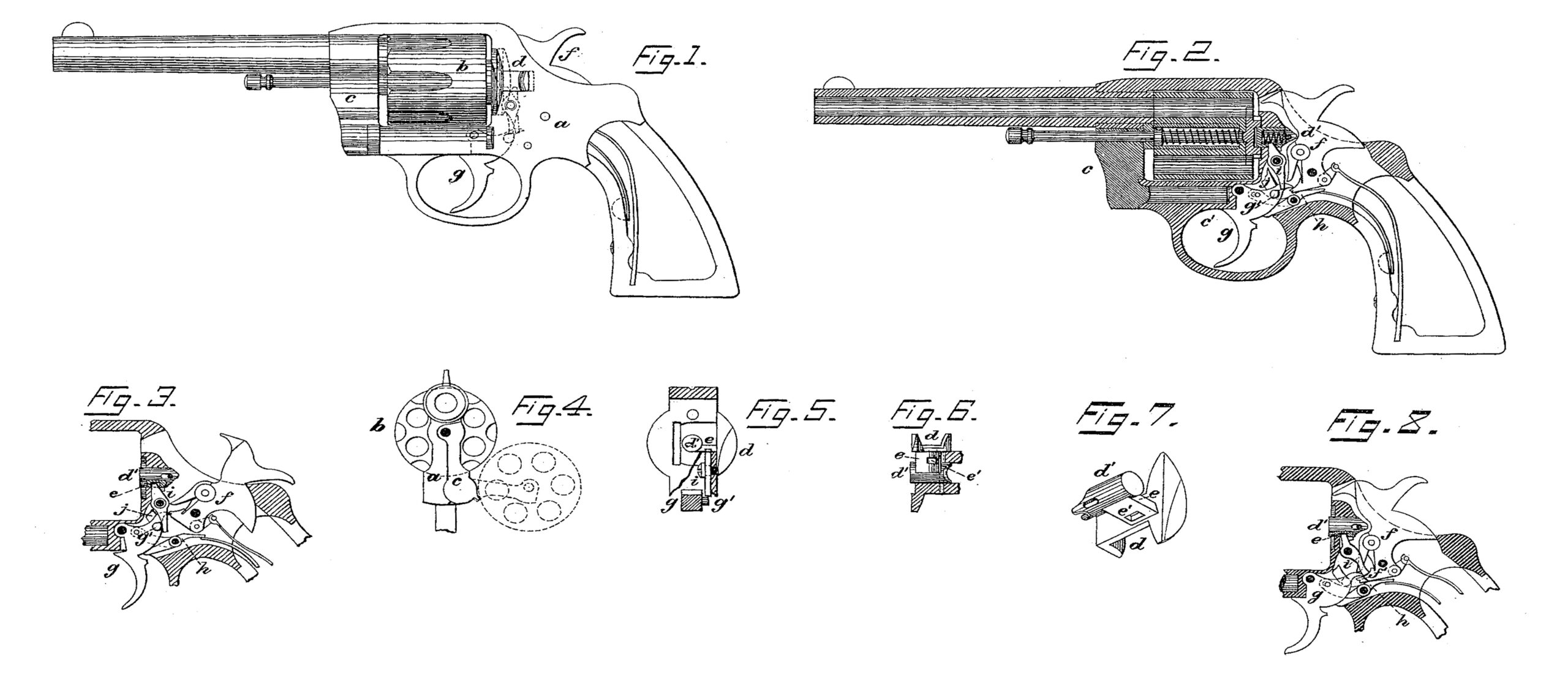
Figure 1, is an elevation of the revolver, showing the cylinder in normal position and the lock at rest. Fig. 2, is a vertical section of the same, with the cylinder and lock as in Fig. 1. Fig. 3 is a vertical section of a part of the revolver, showing the firing mechanism cocked. Fig. 4 is a front end view. Fig. 5 is a transverse section in rear of the cylinder: and Fig. 6 is a horizontal section showing the cylinder latch as seen from below. Fig. 7 is a perspective view of the cylinder latch; and Fig. 8 illustrates a modification.
Similar letters refer to similar parts throughout the several views.
In the frame a is a recess to receive the cylinder b; in rear of which the firing mechanism is arranged, and in front of which the barrel is attached in the usual manner. The forward part of the frame is divided, one portion forming the crane c and the spindle c’ of which, located in a corresponding seat below the cylinder, parallel with the axis of the latter, is the pivot on which said crane may swing laterally. The crane carries the cylinder b on a spindle, so that the cylinder may swing with the crane from the recess in the frame, as shown in dotted lines in Fig. 4, for charging the cylinder or for ejecting the shells, the ejector being of the usual construction.
To secure the cylinder in its normal position in the frame, a sliding latch is provided, which consists, as shown in Figs. 1, 5, 6 and 7 of an exterior slide d, on the left side of the frame, and of a central stem d’ which is in line with the axis of the cylinder and integral with the slide, and is attached to the latter by a short horizontal cross-bare. A thumb-piece on the slide serves to draw it rearward, while a spiral spring within the hollow central stem d’, serves to force the latch forward.
The frame is constructed with the usual recess in its face in rear of the cylinder, for the reception of the cylinder ratchet, and when forward the slide d laterally closes this recess, while the stem d’ enters a central recess in the cylinder-ratchet.
The firing mechanism consists of the hammer f, trigger g, rebound lever h, pawl j, main spring and rebound spring. As far as described the parts and their operations are like those well known in this class of arms and do not require further description.
To prevent the hammer from being cocked when the cylinder is in the frame, unless the latch is fully closed and thus securely holding the cylinder, I place the lever i between the latch d and the trigger g. The lever i is secured within the frame by a screw, on which it turns as on a pivot, its upper arm extending into a recess e’ in the cross bar between the central stem d’ and the slide d of the latch, its lower arm extending to the left side of the trigger g. On the trigger a lateral projection g’ is provided in front of and below the lower arm of the lever i. When the cylinder latch is drawn rearward, as shown in dotted lines in Fig. 1, it moves rearward the upper arm of the lever i and the lower arm of the latter moves forward until its end stands above the lateral projection of the trigger. In this position the lever i positively prevents the trigger from being operated, and as the trigger interlocks with the hammer in the usual manner it is impossible to cock the hammer until the trigger is released by the return of the latch to its forward or closed position, which removes the lever i out of the path of the trigger, Figs. 1 and 2. The lever i also prevents the latch from being moved rearward to release the cylinder, when the hammer has been cocked, for as the hammer is held in the cocked position by the raised trigger, (see Fig. 3,) the projection g’ on the trigger stands in front of the lower arm of the lever i and prevents its forward movement, thus securing the latch in the closed position, until after releasing the hammer when the trigger returns to its lower position. The hammer may be cocked when the cylinder has been entirely swung out of the frame, Fig. 4. As for the ejection of the shells the cylinder must swing out beyond the reach of the latch d, and the latter is moved forward by its spring after the cylinder has passed it; but before the cylinder can be returned to its normal position in the frame, the firing mechanism must be returned to its rest, because the latch d being held in its forward position by the lever i and the projection on the trigger as long as the hammer remains cocked, as described above as shown in Fig. 3, it cannot move out of the path of the cylinder until the hammer and the trigger are released.
I have so far represented the lever connected with the cylinder latch and operating on the trigger; but the free arm of the lever may be constructed to operate on the hammer instead of on the trigger. This modification is shown in Fig. 8, where a lateral projection “f’” is provided on the lower forward part of the hammer “f,” while the trigger has no such projection. The lower arm of the lever “i” is so shaped that its end is above and in Fear of and clears the projection f’ when the firing mechanism is at rest, and the latch closed, while the opening of the latch throws the lever into the path of the projection and the cocking of the hammer brings the projection in front of the lever. I, therefore, do not wish to be understood as limiting my invention to the precise construction shown and described, it only being essential to the invention that the cylinder latch is connected with a lever which interlocks with a movable part of the firing mechanism when the latch is opened.
What I claim as my invention, and desire to secure by Letters Patent, is—
1. In a revolver in which the cylinder is arranged to swing laterally outward and inward from and to its recess in the frame, the combination of a holding device to confine the cylinder in its recess, adapted to be operated at will to release the cylinder and a movable connection between said holding device and the firing mechanism, operated by the movements of said holding device to lock and release the firing mechanism, substantially as set forth.
2. In a revolver the combination of a cylinder arranged to swing laterally outward and inward from and to its recess in the frame, a holding device to confine the cylinder in its recess and adapted to be moved at will to release it, a firing mechanism for said revolver and a lever arranged between said holding device and said firing mechanism, one end of said lever engaging with said holding device and the other with a movable part of the firing mechanism, and said lever being operated by the movements of said holding device to lock and release the firing mechanism, substantially as and for the purpose set forth.
3. In a revolver in which the cylinder is arranged to swing laterally outward and inward from and to its recess in the frame, the combination of a latch on the frame constructed to confine the cylinder in its recess, and adapted to be moved at will to release it, and a lever, connected with said latch and constructed and arranged to stand in the path of a movable part of the firing mechanism so as to prevent the operation of said firing mechanism when the said latch is in the position to release the cylinder, substantially as and for the purpose set forth.
4. In a revolver in which the cylinder is arranged to move laterally outward and inward from and to its recess in the frame, the combination of a latch sliding longitudinally on the frame, so that in the forward position said latch confines the cylinder in the frame, and in the rearward position it releases the cylinder, and a lever pivoted in the frame, one arm of said lever engaging with the latch the other arm extending to the side of the trigger, and a projection on the trigger located in a plane with the lever so that the rearward movement of the latch turns the end of said lever above and against said projection and prevents the operation of the trigger, substantially as and for the purpose set forth.
5. In a revolver in which the cylinder is arranged to move laterally outward and inward from and to its recess in the frame, the combination of a latch sliding longitudinally on the frame, said latch when forward confining the cylinder in the frame, and when rearward releasing it,and a lever pivoted in the frame, the upper arm of said lever extending into a recess in the latch, the lower arm extending to the side of the trigger, and a projection on the trigger in front of and below the lever, the front edge of said lower lever arm constructed parallel to and in rear of the path of said projection on the trigger, when the latch is in the forward position, substantially as and for the purpose set forth.
This specification signed and witnessed this 24th day of March, A. D. 1894.
FRANK B. FELTON.
In presence of—
JAS. F. BRYANT,
C. J. EHBETS.