
US 565678
UNITED STATES PATENT OFFICE.
CHARLES E. FOSTER, OF WASHINGTON, DISTRICT OF COLUMBIA, ASSIGNOR
TO DANIEL B. WESSON, OF SPRINGFIELD, MASSACHUSETTS.
SAFETY DEVICE FOR REVOLVERS.
SPECIFICATION forming part of Letters Patent No. 565,678, dated August 11, 1896.
Application filed April 14, 1892. Serial No. 429,203. (No model.)
To all whom it may concern:
Be it known that I, CHARLES E. FOSTER, a citizen of the United States, and a resident of Washington, in the District of Columbia, have invented certain new and useful Improvements in Firearms, of which the following is a specification.
The object of my invention is to prevent the explosion of the cartridge of a firearm, except when the latter is properly grasped for the purpose of firing, and to this end I provide the arm with a slide so constructed as when in the normal position to obstruct the movement of some part of the arm with a spring for maintaining the slide normally in this position, and with a head upon the slide projecting beyond the frame or stock in such position that the head will be pressed upon only when the arm is grasped for the purpose of firing, and the slide will thereby be moved to & position to no longer obstruct the operation of the firing mechanism, all as set forth hereinafter, and as illustrated in the accompanying drawings, In which—
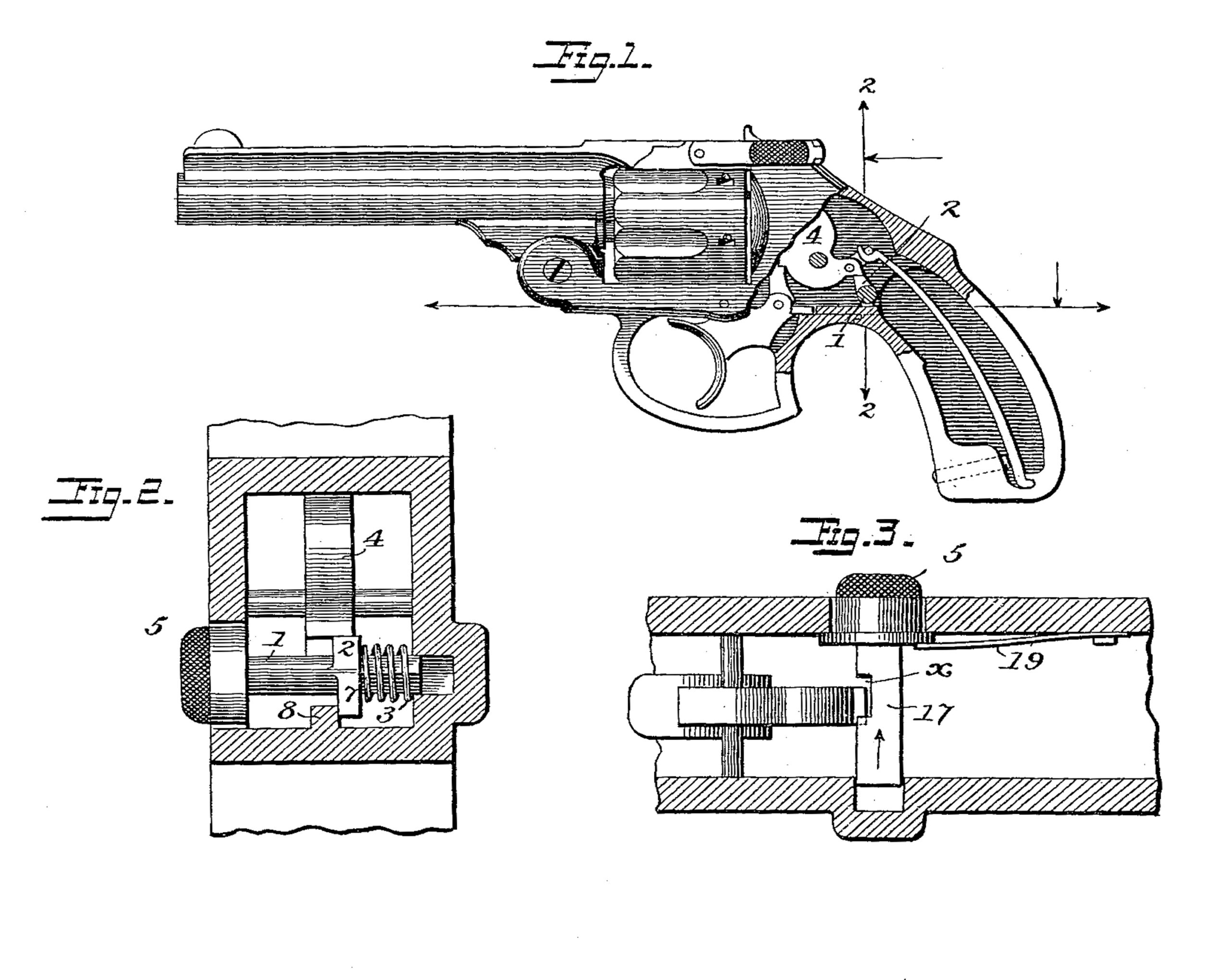
Figure 1 is a sectional elevation of sufficient of a pistol to illustrate my improvement. Fig. 2 is a section transversely on the line 2 2 of Fig.1. Fig.3 is a sectional elevation illustrating a modification.
Heretofore firearms have been provided with levers actuated by springs in one direction and by pressure of the hand in the other, and so constructed and arranged as when in their normal position to lock some portion of the firing mechanism. The object of this arrangement is to prevent the premature firing of the arm, but an objection to the construction is that the levers must be of considerable length and consequently of greater or less flexibility, so that they can yield to a certain extent when pressure is applied to the firing mechanism, and they are liable to be vibrated by jars or blows upon the arm. By the construction which I will now describe I avoid these objections.
The improved safety device may be applied to either pistols or rifles or any other kind of hand-arms. As shown in the drawings, it is in connection with an ordinary revolving pistol.
The trigger, hammer, and other usual parts of the pistol may be arranged in the frame as usual and of any suitable construction in connection either with a revolving cylinder or any other means of supporting the cartridges and presenting them in line with a barrel. In connection with the aforesaid parts as embodied in any of the usual constructions I make use of a slide so arranged that in its normal position it will present an obstruction to the withdrawal of the hammer or to the movement of some part connected with the hammer for the purpose of shifting the position of the same for firing.
As shown in the drawings, the sliding stop is so arranged that a portion of the same will extend beneath the tail of the hammer when the parts are in their normal position, and will thereby prevent the hammer from being drawn back, and in said figures the lateral sliding of the stop will carry the contacting part away from beneath the tail of the hammer, and in the construction illustrated more particularly in Fig. 3 the stop slides normally into position to obstruct the mechanism of the trigger, but may be moved laterally to permit the trigger to swing upward.
In the construction shown in Figs. 1 and 2 there is a cross-bar 1, provided with a head 5, which latter extends into and projects outward beyond an opening in the side of the cheek of the frame of the pistol, the inner end of the bar 1 extending into a recess in the opposite frame, and a lug 2 upon the said bar is so arranged that when the bar is at its extreme position at the left the lug is beneath the tail of the hammer 4 and so close thereto that the hammer cannot be drawn back. The recess into which the inner end of the cross-bar 1 is received is closed at the outer side of the handle of the firearm, as shown, and this construction prevents the said cross-bar from being forced outward beyond the side of the handle, which, if not provided for, would produce an unnecessary obstruction to the proper handling of the firearm for the purposes of firing. It will be seen, furthermore, that the lug 8 constitutes independent means for limiting the outer movement of the cross-bar in a direction opposite to that of the said inner recess, this construction distinguishing from former constructions wherein such limit of movement is effected by part of the firing mechanism itself. A spring 3 is between the side of the frame and the lug 2, and serves to throw the bar 1 to the limit of its movement toward the left, projecting the head 5 to its maximum extent beyond the cheek of the pistol, as limited by a lug 7 on the bar 1 making contact with a lug 8, constituting part of the frame. The head 5 is of such an extent and so arranged that when the pistol is taken in the hand in the position required for firing the side of the thumb will bear upon the said head and throw the sliding bar 1 inward toward the right, Fig. 2, thereby carrying the lug 2 away from beneath the tail of the hammer and permitting the latter to be moved by the ordinary mechanism.
In the modification shown in Fig. 3 the slide is in the form of a plate 17, which slides in a recess in the frame just back of the trigger 8, and said sliding plate has a notch x, which, when the plate is pushed in, is opposite the edge of the trigger and permits the latter to move to operate the hammer, but when the sliding plate 17 is thrown in the direction of the arrow, Fig. 3, by the pressure of a spring 19, a part of the sliding plate is brought above a shoulder of the trigger and prevents the latter from being moved. Upon the end of the sliding plate 17 is a head 5, upon which the forefinger presses when the piston is seized for firing.
It will be evident that a stop sliding either forward and back or transversely of the stock may be arranged in different ways and carry a projecting part which by one movement is carried opposite some operative part of the mechanism and prevents the pistol from being operated, while by another movement it is carried away from such part to allow it to be operated as usual. It is essential that the head 5, whatever may be the character of the side employed, shall be so arranged that when the pistol is seized for firing it will be pressed upon by some part of the hand or fingers, but that when the pistol is being handled in the ordinary way, without any attempt to fire, there shall be little or no liability of the head 5 being pressed inward at the same time that the trigger is pulled or the hammer is manipulated or pressed upon in any way.
Without limiting myself to the precise construction and arrangement of parts set forth and illustrated I claim—
The combination in a firearm having in one side of the handle thereof an opening, and in the other side an inner recess which is closed on the outer side of the handle, of a slide with its inner end working in said recess, and its outer end provided with a head normally projecting outward through said opening, a spring for pressing the slide outward in one direction, and the means independent of the firing mechanism for limiting said outward movement and comprising the lugs 7 and 8, the said slide being normally in engagement with some part of the firing mechanism when the slide is locked, substantially as shown and for the purposes described.
In testimony whereof I have signed my name to this specification in the presence of two subscribing witnesses.
CHARLES E. FOSTER.
Witnesses:
J. S. BARKER,
G. P. KRAMER.