
US 642688
UNITED STATES PATENT OFFICE.
ANDREW FYRBERG, OF WORCESTER, MASSACHUSETTS.
SAFETY-LOCK MECHANISM FOR FIREARMS.
SPECIFICATION forming part of Letters Patent No. 642,688, dated February 6, 1900.
Application filed September 5, 1899. Serial No. 729,571. (No model.)
To all whom it may concern:
Be it known that LANDREW FYRBERG, a citizen of the United States, residing at Worcester, in the county of Worcester and State of Massachusetts, have invented a new and useful Improvement in Safety-Lock Mechanism for Firearms, of which the following is a specification.
My invention relates to improvements in safety-lock mechanism for firearms in which an automatically retracting and oscillating firing-pin operates in conjunction with an indented hammer and the trigger-pawl that cock said hammer or actuates it against the mainspring; and the objects of my improvement are, first,-to provide a safety-lock mechanism especially adapted for double-acting pistols, an automatically-retracting firing-pin being so arranged as not to be affected by any accidental movement of the hammer or of the trigger, except at the instant of the forward plunge of the former; second, to furnish a cartridge-discharging device that is operative only when the trigger is drawn back to the end of its stroke, and, third, to render the mechanism simple, durable, and positive. I attain these objects by the mechanism illustrated in the accompanying drawings, in which—
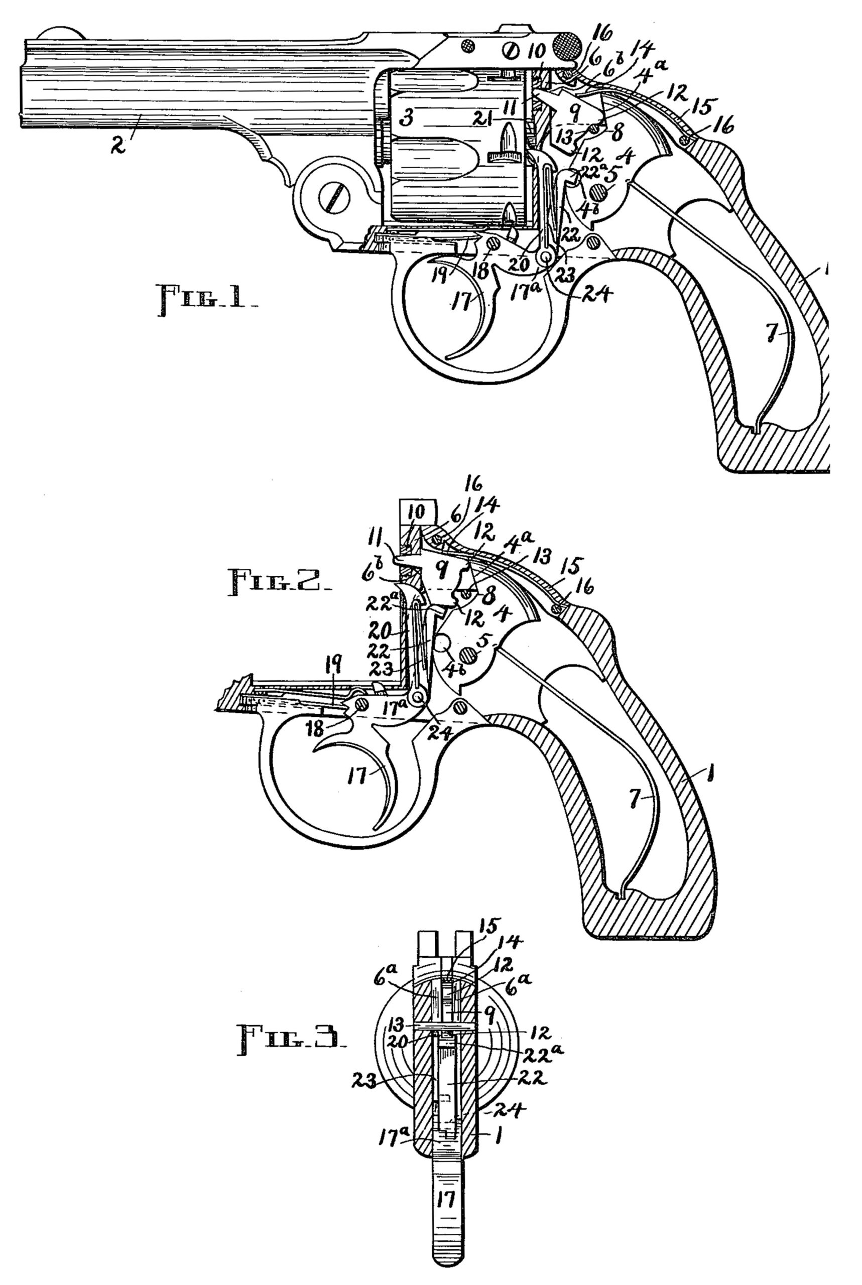
Figure 1 is a longitudinal section of the stock and frame of a revolver, showing my invention incorporated therewith, the several parts being normally disposed and inactive; Fig. 2, a similar view with said parts disposed as at the instant of firing,’the barrel and cylinder being here omitted, which leaves no support for the pawl that rotates said cylinder; but it will be understood, of course, that the point of said pawl constantly engages the cylinder-ratchet, which thereby supports the pawl; and Fig. 3, a transverse vertical section taken between the firing-pin and the hammer in Fig. 2.
Similar figures refer to similar parts throughout the several views.
The pistol-frame 1 of suitable form has the barrel 2 and the cylinder 3 connected therewith and operated in the usual manner. The hammer 4 is pivoted at 5 within the frame 1 and behind that portion of said frame termed the “recoil-block” 6, which arrests its forward movement. The mainspring 7 normally retains the striking-face 4a of the hammer 4 in contact with the rear edges 6a of the block 6. Said hammer is cut away or indented at 8 to give clearance for the rear of the firing-pin 9, only the upper part of the latter being engaged by the striking-face 4a. The recoil-block 6 is provided with the opening 6b through which the firing-pin operates, said opening being small in front and wider vertically in the rear with parallel sides. A bushing 10 may be inserted in the front of the block 6 to strengthen the same, and the opening 6b extends through this bushing.
The firing-pin 9 consists of a flat body, the forwardly-projecting nose 11, and the rearwardly-extending cars 12 12. The pin 9 cannot rotate in the recoil-block opening 6b, but has a triangular sliding motion therein, the whole having a longitudinal movement, while the rear end oscillates or swings up and down sufficiently, on the one hand, to receive a blow from the hammer 4, and, on the other, to be protected from the same by the edges 6a of the recoil-block 6. The firing-pin nose 11 fits loosely in the forward part of the opening 6b, through which it is advanced to discharge the cartridge, being retracted thereafter, and said nose serves in a measure as a fulcrum from which the oscillating action of said pin takes place. The pin or stop 13 is inserted in the frame 1 below the rear portion of the block 6 to limit-the swinging and backward action of the firing-pin 9. The firing-pin is normally retained with the upper car 12 resting on the stop 13 and the nose 11 wholly within the opening 6b by means of the flat spring 14, which is attached to the block 15, inserted in a slot in the top of the frame 1 and securely held in place by the pins 16 16. The free terminal of the spring 14 bears on the upper edge of the pin 9 and constantly tensions said pin downward and rearward. It is obvious that a different spring or a different arrangement of the same spring will accomplish the same purpose as that shown and above described. Hence I do not wish to confine my invention to the use of any particular resilient medium in this connection.
The trigger 17 is pivoted in the usual manner at 18 to the frame 1 and normally pressed forward by a suitable trigger-spring 19, the heel 17a of said trigger being thereby depressed. The pawl engages the ratchet-teeth 21 on the cylinder 3, and the pawl 22 has the beak 22a to register with the notch 4b in the hammer 11, the spring 23 serving to separate said pawls and force the last-mentioned pawl against the front edge of said hammer. Said pawls are pivoted at 24 to the triggerheel 17a.
The operation of my device is as follows: When the parts are disposed normally, as illustrated in Fig. 1, the firing-pin 9 is held out of position necessary for execution by the spring 14 being at the extreme of its backward and downward travel, with the upper ear 12 in contact with the stop 13. The hammer 4 bears against the edges 6a and no accidental or irregular action of the same can affect the firing-pin, because it is within the opening 6b, back as well as front. When the trigger 17 is drawn back, the heel 17 rises, and through the medium of the pawl 22, which engages the hammer 4 at this time, operates the latter against its spring 7, causing the striking-face 4b to recede from the recoil-block 6. The upward movement of the pawl 22 causes it to engage the base of the firing-pin 9 and swing said pin upward against the resiliency of the spring 14. The upper car 12 now projects out of the block 6 and receives the force of the blow struck by the hammer 4 as the pawl-beak 22a slips out of the notch t and releases said hammer, which plunges forward under the action of the spring 7. The pawl 22 is rocked forward against the force of the spring 23 by the hammer 4 after the beak 22a passes out of the notch 4b, but still supports the firing-pin. The blow of the hammer drives the firing-pin forward and explodes the cartridge, the parts standing as illustrated in Fig. 2. Upon the release of the trigger 17 the pawl 22 drops away from the firing-pin to re-engage the hammer, the spring 14 depresses the rear end of said firing-pin and actuates it backward into engagement with the stop 13, and the several parts stand in their original positions. The hammer indentation 8 permits of the various motions incidental to the operation of the firing-pin without danger of wedging or binding the same.
I am aware that the idea of controlling a safety device by the trigger is not new, such feature having been employed in various differently-constructed mechanisms. Hence it will be understood that I do not broadly claim such means; but my invention comprises the construction and organization of mechanism specifically as illustrated and defined.
What I do claim as my invention, and desire to secure by Letters Patent, is-
1. In a firearm, in combination, a firing-pin confined in a recoil-block and having end-wise motion and an up-and-down motion at the rear, a trigger-pawl unattached to said firing-pin and adapted to actuate the rear of the latter upward into the path of the stroke of the hammer at the instant it plunges forward, and resilient means for returning said firing-pin to its normal position within said recoil-block, substantially as set forth.
2. In a firearm, in combination, a firing-pin confined in a recoil-block and having endwise motion and an up-and-down motion at the rear, a stop arranged to limit the backward and downward movement of said firing-pin, a trigger-pawl unattached to said firing-pin and adapted to actuate the rear of the latter in to the path of the stroke of the hammer at the instant it plunges forward, and resilient means for returning said firing-pin to its normal position against said stop, substantially as set forth.
3. In a firearm, in combination with an indented internal hammer having its striking-face normally bearing against the recoil-block, a spring-retracted firing-pin confined in said recoil-block and having endwise motion and an np-and-down motion at the rear, and a trigger-pawl unattached to said firing-pin and adapted to actuate the rear of the latter into the path of the stroke of said hammer at the instant it plunges forward, the firing-pin otherwise operating freely in the hammer indentation, substantially as set forth.
4. In a firearm, in combination with an indented internal hammer having its striking-face normally bearing against the recoil-block, a spring-retracted firing-pin confined in said recoil-block and having endwise motion and an up-and-down motion at the rear, a stop arranged to limit the backward-and-downward movement of said firing-pin, and a trigger-pawl unattached to said firing-pin and adapted to actuate the rear of the same into the path of the stroke of said hammer at the instant it plunges forward, the firing-pin otherwise operating freely in the hammer indentation, substantially as set forth.
5. In a firearm, the recoil-block portion of the frame provided with an opening small in front and vertically enlarged in the rear, having internal parallel sides; in combination with a firing-pin consisting of a flat body having a rounded forwardly-projecting nose supported in the small part of said opening, and rearwardly-extending ears, said fiat body arranged to move up and down between said sides; a stop behind said body; a spring to retract and depress said firing-pin; and a trigger-pawl unattached to said firing-pin and adapted to rise beneath the rear end of the latter to elevate the same, substantially as described.
6. The combination, in a firearm, of an automatically retracting and oscillating firing-pin confined in a recoil-block, a stop behind the former, an indented internal hammer normally in contact with said recoil-block, a main-spring for the hammer, a pivoted trigger influenced by a trigger-spring, and a spring-actuated pawl adapted to operate said hammer and to actuate said firing-pin into the path of the stroke of said hammer at the instant the latter plunged forward, substantially as described.
ANDREW FYRBERG.
Witnesses:
W. H. TINCHELL,
F. A. CUTTER.