
US 647861
UNITED STATES PATENT OFFICE.
CHRISTOPHER D. McDONALD OF VANCE, COLORADO.
REVOLVER.
SPECIFICATION forming part of Letters Patent No. 647,861, dated April 3, 1900.
Application Filed July 25, 1899. Serial No. 725,091. (No model.)
To all whom it may concern:
Be it known that I, CHRISTOPHER D. McDONALD, of Vance, in the county of San Miguel and State of Colorado, have invented a new and useful improvement in Revolvers, of which the following is a specification.
My invention is in the Raire of an improvement in firearms of the class know as “revolvers;” and its object, is to provide means for breaking or opening the arm and ejecting the empty cartridge-shells from the cylinder, to the end that reloading may be accomplished with the greatest facility and in the shortest space of time.
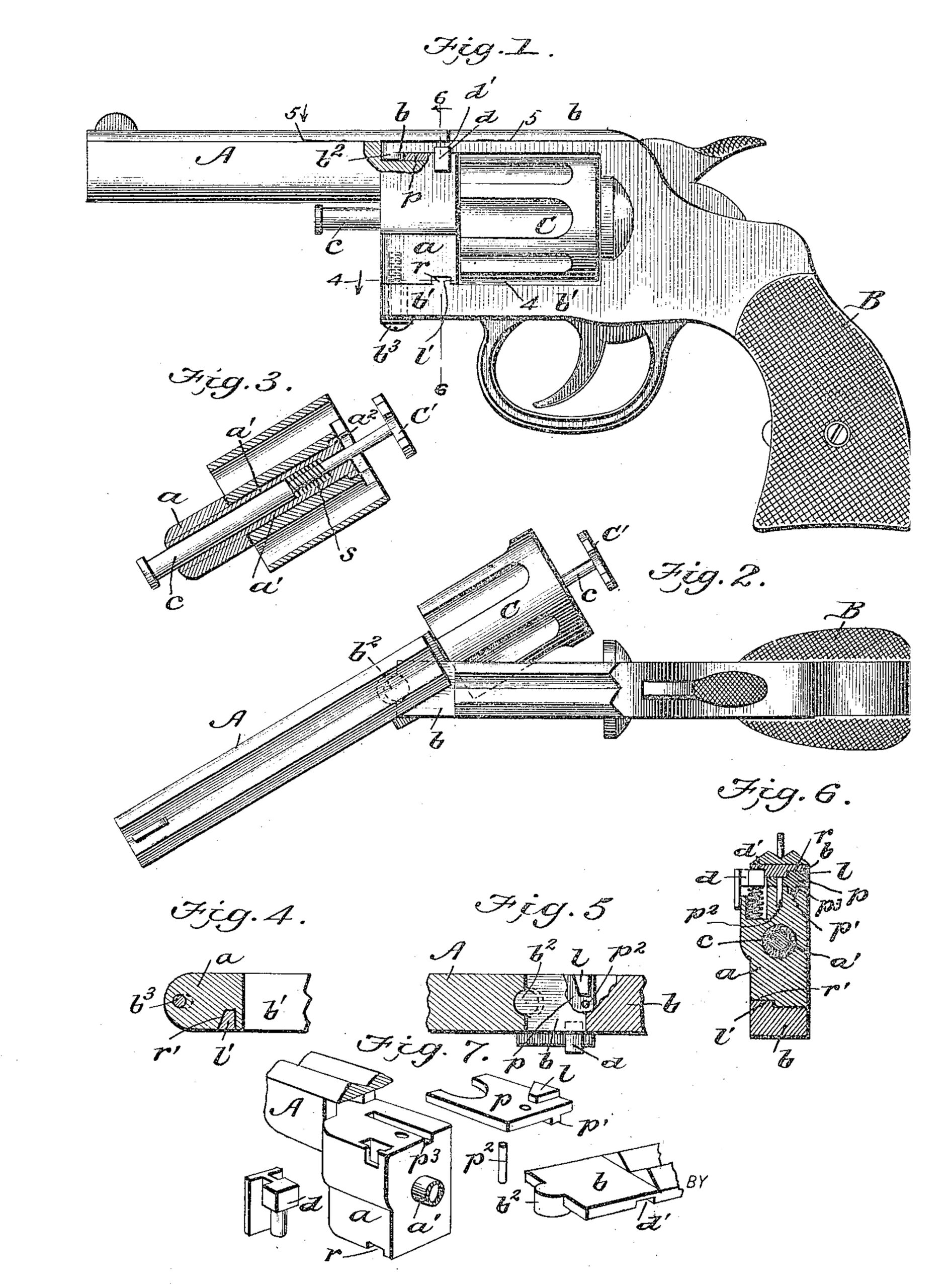
It consists in the peculiar construction and arrangement of the parts, as will be hereinafter shown and described, reference being had to the accompanying drawings,in which Figure 1 is a side view, partly in section. Fig. 2 is a plain view with the revolver opened. Fig. 3 is a horizontal section through the cylinder, the parts being in the position of Fig. 2. Fig. 4 is a detail section on line 4 4 of Fig. 1, and Fig. 5 a similar view on the line 5 5, showing the stop-lugs for stopping and tightening the barrel in alignment with the cylinder. Fig. 6 is a cross-section on line 6 6 of Fig. 1, and Fig. 7 shows details in perspective of the parts of the break-joints.
In the drawings, A represents the barrel portion of the revolver, B the handle, and C the cylinder in which are formed the cartridge-chambers.
The barrel portion A is made with a thickened abutment a, from the rear of which projects the rigidly-attached sleeve a’, which swivels in the center of and forms the axis of revolution for the cylinder C, which latter is prevented from coming of by an enlarged head a2. Centrally through the abutment a of the barrel and the sleeve a’ there extends a sliding stem c, which has a knob or enlargement on its forward end and at its rear end is rigidly attached to the scalloped ejector-head C’, which lies within a recess at the rear of the cylinder, with it scallops completing the periphery of the chambers and underlying the flanges of the cartridge-shells as is common. This stem is pressed forwardly by a helical spring s, bearing against a shoulder on the stem, so as to hold the ejector down in its recess; but when said stem is pressed to the rear the ejector is thrown out, carrying the cartridge-shells with it, as shown in Fig. 3.
The barrel and its abutment a, carrying the cylinder, are hinged to forwardly-extending branches b b’ of the handle portion about a vertical axis formed by knuckle-joint b2 at, top and pivot-screw b3 at the bottom, the two being arranged in vertical alinement.
To lock the barrel in alignment with the branches b b’ of the handle, a spring-seated locking-bolt, d is arranged in a recess in the abutment a is adapted to enter a recess d’ in the upper branch b of the handle.
To stop the barrel in alignment with the branches b b’ of the handle, cam-lugs are arranged at the joint, at top and bottom. One of these cam-lugs l’ is formed on the upper surface of the lower branch b’ of the handle and enters a recess r’ in the lower side of the abutment a, and the other lug l is formed on the upper surface of a plate p on the top of the abutment and enters a recess in the lower surface of the upper branch of the handle on the opposite side of the revolver. These lugs l l’ have cam-faces, as seen in Figs. 4 and 5, which cause the barrel and cylinder, on the one hand, and the handle and its branches, on the other, to be drawn tightly toward each other when the joint is closed and the barrel and handle are in alinement.
To enclose the knuckle-joint b2 at the top and permit the parts to be put together, the plate p is provided. This has a longitudinal rib p’ on its lower side, that slides into a groove p3 in the top abutment, a, and a pin p2 locks the plate in place. This plate engages with a boss formed on the lower side of the forward end of the handle branch b and forms the upper joint about which the barrel is articulated.
With this construction of revolver the barrel may be grasped in the left hand, the locking-bolt d pressed down with the thumb, and the barrel being defected with the cylinder the forefinger of the same hand may be pressed against the spring-seated stem of the ejector to discharge the shells in a most rapid, convenient, and effective manner, the right hand being employed to fill the cylinder with fresh cartridges.
Having thus described my invention, what I claim as new, and desire to secure by Letters Patent, is—
1. A revolver consisting of a handle portion having a rigidly-attached upper and lower extension inclosing the cylinder-space, and a barrel hinged on a vertical axis between the forward ends of said rigid extensions and bearing a revolving cylinder substantially as and for the purpose described.
2. The combination in a revolver, of a handle portion having an upper and lower extension, a barrel hinged between the forward ends of the same to swing sidewise and carrying the cylinder, and a spring-seated locking-bolt for locking the barrel and handle in alignment as described.
3. The combination in a revolver, of a handle portion having an upper and lower extension, a barrel hinged between the forward ends of the same to swing sidewise and carrying the cylinder, a spring-seated locking bolt for locking the barrel and handle in alinement, and cam-lugs for drawing the parts together when in closed position.
4. The combination in a revolver, of a handle portion having an upper and lower extension, and a barrel hinged between the forward ends of the same to swing sidewise, its upper hinge-joint, being in the form of a knuckle having a detachable retaining-plate p substantially as and for the purpose described.
5. A revolver having rigid handle extensions both above and below the cylinder, and a barrel jointed to the forward ends of the same, said barrel having on one side of its rear end a lateral projection with a recess in the same, and a locking-bolt playing in said recess, and locking against the edge of the upper forward extension from the handle, and a spring arranged beneath said locking bolt in said recess, substantially as described.
CHRISTOPER D. MCDONALD.
Witnesses:
WINFIELD S. CARHART,
CHAS. ELLIOTT.