
US 650931
UNITED STATES PATENT OFFICE.
CARL J. EHBETS AND JAMES J. PEARD, OF HARTFORD, CONNECTICUT, ASSIGNORS TO THE COLT’S PATENT FIRE ARMS MANUFACTURING COMPANY, OF SAME PLACE.
CYLINDER-STOP FOR REVOLVERS.
SPECIFICATION forming part of Letters Patent No. 650,931, dated June 5, 1900.
Application filed July 14, 1899. Serial No. 723,815. (No model.)
To all whom it may concern:
Be it known that we, CARL J. EHBETS and JAMES J. PEARD, citizens of the United States, residing at Hartford, in the county of Hartford and State of Connecticut, have invented new and useful Improvements in Revolving Firearms, of which the following is a specification.
Our invention relates to improvements in revolving firearms and pertains to the firing mechanism thereof.
The objects of our improvements are to provide in a revolver a simple but efficient device for locking the cylinder against rotation when the firing mechanism is in the normal position of rest, also when it is in the cocked position ready for firing, during the act of firing, and while the firing mechanism is returned to the normal position of rest, and for releasing the cylinder for free rotation when the firing mechanism is operated and while it is brought from the position of rest to the cocked position ready for firing.
Our invention is more particularly set forth in the claims hereinafter following, forming a part of this specification, embodiments thereof being comprised in the parts and mechanisms and in the combination of parts and mechanisms and their operations hereinafter described, and illustrated in the accompanying drawings, in which—
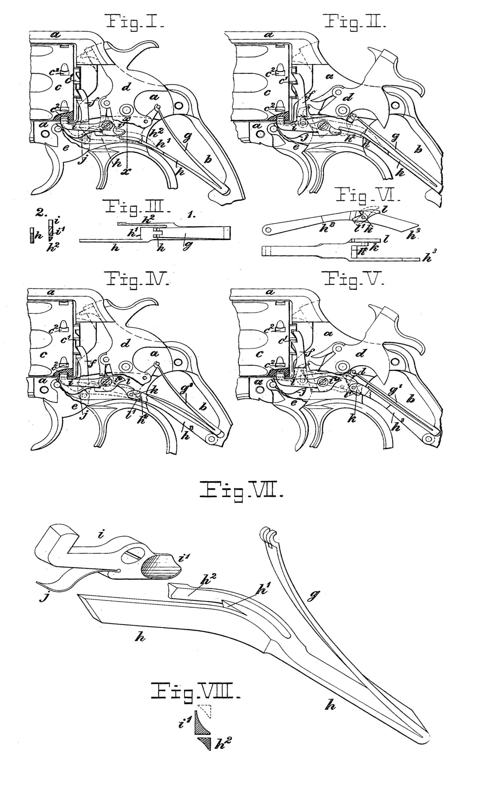
Figure I is a partial side elevation of a revolving firearm with the side plate and the left-hand cheek-piece removed to expose to view the firing mechanism in the position of rest, certain portions of the members of the firing mechanism being broken away to more clearly show the cylinder-stop, the broken-away portions being represented with dotted lines. Fig. II is a similar view of the same, but showing the firing mechanism in the cocked position ready for firing. Fig. III shows detail views— at 1 a top view of the combined mainspring and rebound-lever detached and at 2 a rear view of the cylinder-stop detached and a vertical transverse section of the rebound-lever on the line x x of Fig. I. Fig. IV is a partial side elevation similar to Fig. I, but showing a certain modified form of the cylinder-stop and of the rebound-lever hereinafter further explained. Fig. V is a similar view of the same, but showing the firing mechanism in the cocked position ready for firing. Fig. VI shows a right side view of the modified rebound-lever detached and an under side view of the same. Fig. VII is a perspective view of the cylinder-stop and of the combined mainspring and rebound-lever, upon an enlarged scale, in their relative positions when the firing mechanism is at rest, as in Fig. I. Fig. VIII represents, upon an enlarged scale, a vertical transverse section through the rear portion i’ of the cylinder-stop and through the lever-arm h2 in their relative positions, as in Fig. I, the alternate position of the lever-arm h2 above the cylinder-stop being indicated by dotted lines.
Similar letters and figures refer to similar parts throughout the several views.
In the drawings, a indicates the frame, and b the grip, of a revolver from which the detachable side plate and the left-hand cheekpiece of the grip have been removed to show the members of the firing mechanism mounted in the frame. c is the revolving cylinder arranged in its recess in the frame. In rear of the cylinder the hammer d is pivoted, and below it the trigger e, while pivotally mounted in the trigger is the pawl f, extending upward to the ratchet c’ of the cylinder. Mounted in the grip are the mainspring g and the rebound-lever h, which extend forward and are operatively connected, respectively, with the hammer and with the trigger and pawl. All these parts are arranged and operate in the well-known manner usual in arms of this class.
In a recess within the right side of the frame the cylinder-stop i is pivoted and, extending forward, is provided with a nose projecting upward through an opening into the cylinder recess and into one of a series of corresponding notches c provided in the circumference of the cylinder. The cylinder-stop spring j serves to yieldingly hold the forward part of the cylinder-stop i in the raised position and its nose in engagement with the cylinder, thereby preventing rotation of the same.
In Figs. I, II, IV, and V a portion of the cylinder is represented in section, showing the engagement of the cylinder-stop with the cylinder, and the lower portion of the hammer d and of the pawl f, the rear portion of the trigger e, and the forward left-hand portion of the rebound-lever h, which in these figures overlie the cylinder-stop, have been broken away, and the broken-away portions of these members are indicated by dotted lines.
In the form of the cylinder-stop shown in Figs. I, II, III, VII, and VIII the under engaging surface of the rear portion i’ of the cylinder-stop is flat, and such portion is of a uniform thickness at its lower edge; but it is beveled toward the top, so that its inner left side, nearest to the hammer, inclines upward and outward. In these figures we have shown the mainspring and the rebound-lever combined to one integral whole, of which the upper arm g is pivotally connected with the stirrup of the hammer, while the forward portion of the lower arm h is divided into two arms, between which it forms the shoulder h’, which bears against the rear of the hammer below its pivot and serves to force the hammer to the rebounded position and to retain it there when the trigger has been released, as in Fig. I.
Forward of the shoulder h’ the left lever arm, as indicated in Figs. I and II by dotted lines, extends by the side of the hammer, and its end, being beveled to incline upward and forward, rests upon a shoulder provided on the cylinder-pawl above the pivot, by which the pawl is connected with the trigger. Thus this left arm of the rebound-lever h serves to yieldingly press the cylinder-pawl forward against the cylinder-ratchet and the trigger downward to its normal position. As we require for the operation of the cylinder-stop a lever-arm independent of the hammer and of the trigger, but actuated and moving with the firing mechanism, we have utilized the said rebound-lever for this purpose. However, a similar lever-arm connected with the firing mechanism, as shown and described, but not provided with means for effecting the rebound of the hammer, would serve our purpose as well. On the other side of the hammer the right arm h2 of the rebound-lever extends forward to beneath the cylinder-stop. It is vertically rigid; but, as shown in the top view 1, Fig. III, and in Fig.VII, for some distance forward of their union the right arm h2 and the rebound-lever h are separated by a vertical opening, and the arm h2 tapers from the rear forward,so as to make it laterally flexible. By this construction the arm h2, while integral with the rebound-lever h and moving vertically with said lever, forms a spring adapted for lateral motion independent of the rebound lever. As shown in the transverse section 2, III, and in Figs. VII and VIII, at its free end the arm h2 is beveled on the outside, inclining down and inward, while its upper engaging surface is flat.
From the above description of the parts their operations will be readily understood. When the firing mechanism is brought from the position of rest, as in Fig. I, to the cooked position, as in Fig. II, by cooking the hammer either directly by means of its thumb-piece or by operating the trigger the movement of the trigger causes the cylinder-pawl, pivoted to the trigger, to move upward, and as the forward end of the lever-arm h rests upon a shoulder on the cylinder-pawl the rebound lever h is raised by the upward movement of the cylinder-pawl from the position in Fig. I to that in Fig. II. At the commencement of this upward motion the arm h2 engages the cylinder-stop i, and, raising the rear of the stop, lowers its forward arm and withdraws its nose from the cylinder-recess, and thus releases the cylinder, so as to be free for rotation when the cylinder-pawl engages the cylinder-ratchet. The flat surfaces on the top of the arm h2 and on the bottom of the cylinder-stop i make this engagement of these parts positive. As the cooking movement continues the end of the arm h2 travels along the edge of the stop i and keeps the latter in the released position until the end of the arm h2 passes by and above that of the stop i, thereby releasing the latter, which is at once returned to its normal position by the spring j. The release of the stop and its return take place just before the hammer is fully cocked, and before the cylinder completes its parti-rotation, so that before the hammer can fall and fire a shot the nose of the stop has entered the corresponding notch in the cylinder and the latter is positively locked in the firing position against rotation in either direction. When after releasing the hammer the trigger is released, the pressure of the combined mainspring and rebound-lever rebounds the hammer and returns the trigger to the normal position. During this return movement the arm h2 moves from above the stop i to below the same, the beveled outer side of the arm h2 engaging the inner side of the rear portion i’ of the stop i, which is likewise beveled, as heretofore explained, and the flexibility of the arm h2 allows the latter to yield laterally and inward until it has passed by the stop, when it resumes its first position beneath and in line with the stop.
While we prefer to make the stop i laterally rigid and the right arm h2 of the rebound lever flexible, as shown and explained, this construction maybe reversed by making the lever-arm rigid and the rear portion of the cylinder-stop flexible, an arrangement which the firing mechanism remain unchanged with the exception of the rebound-lever and the cylinder-stop.
In Figs. IV, V, and VI we have illustrated a modification in which all the members of the firing mechanism remain unchanged with the exception of the rebound-lever and the cylinder-stop. We have in these figures shown the mainspring g’ separated from and resting upon the rebound-lever h3, which is pivotally attached in the grip; but this well known arrangement of these parts is not essential to the construction and does not affect the operation of the modified members. The cylinder-stop i is constructed and pivoted in the frame as heretofore described; but the part i2 in rear of its pivot is cam shaped, of uniform thickness, and laterally rigid. The rebound-lever h3 remains unchanged in shape and operation as to the shoulder hand as to the left arm extending from the shoulder to the cylinder-pawl and trigger; but on the right side of the shoulder h4 instead of carrying the flexible arm h2 the rebound-lever is provided with a short rigid projection k, to the outside of which the dog l is attached by a transverse pivot, so as to freely turn thereon in a vertical plane. (See Fig. VI.) A shoulder on the lever in rear of the dog and a tail l’, projecting downward from the dog, serve to limit the motion of the same. In the right side view of the rebound lever, Fig. VI, the dog l is plainly shown in the normal position, and its raised position is indicated with dotted lines. The operation of these parts is as follows: In the normal position of the firing mechanism at rest, as in Fig. IV, the rebound-lever h3 is in the lowest position and the dog l stands beneath the end i’ of the cylinder-stop i. When the firing mechanism is operated and the rebound-lever is raised, the point of the dog l engages the cylinder-stop i and releases the cylinder until as the hammer approaches the cooked position, as in Fig. V, the point of the dog l passes by and above the end i2 of the cylinder stop i, thereby releasing the same, when the spring j at once raises the nose of the cylinder-stop and locks the cylinder. When on the release of the trigger the pressure of the mainspring returns the rebound-lever and the trigger to the lower position, the point of the dog l strikes against the top of the end i2 of the cylinder-stop i and the dog yields by turning upward on its pivot until stopped by the shoulder in rear of it on the lever. At this point the downward movement of the rebound-lever and the upward movement of the dog enable the point of the dog to clear and pass downward by the end of the cylinder-stop. As the rebound-lever approaches its normal position the tail l’ of the dog strikes against the inside of the frame a, and during the last of the return movement the dog l is positively returned from the raised to its lowest position beneath the cylinder-stop, Fig. IV, ready again to engage the same at the next operation. By this construction we avoid the use of an additional spring, as it enables us to operate the cylinder-stop by the upward movement of the lever and during its downward movement to let the lever pass idly by the cylinder-stop without making a part of the lever flexible and without the use of a spring between the lever and the dog for turning down the dog to its normal operative position.
What we claim as our invention, and desire to secure by Letters Patent, is—
1. In a revolving firearm, the combination with the cylinder and cylinder-stop, of a rebound-lever having an arm to engage the cylinder-stop and operate the same.
2. In a revolving firearm, the combination with the cylinder and cylinder-stop, of a rebound-lever having an arm to engage the cylinder-stop while moving in one direction and pass idly by the same while moving in the opposite direction.
3. In a revolving firearm, the combination with the cylinder and cylinder-stop, of a rebound-lever having an arm with a part which engages the cylinder-stop while moving in one direction and yields to pass the same idly while moving in the opposite direction.
4. A rebound-lever for a revolving firearm having an arm with a dog pivotally mounted thereon to engage in one direction and pass idly by the cylinder-stop.
5. In a revolving firearm, a cylinder-stop pivoted in the frame in rear of the cylinder and provided with means for locking and yieldingly holding said cylinder-stop in the locked position, in combination with a bifurcated rebound-lever and a mainspring, one branch of said rebound-lever extending to and actuating the cylinder-pawl and the trigger, the other branch extending to said cylinder-stop, to unlock and to release the same, substantially as and for the purpose described.
6. In a revolving firearm, the combination with the cylinder, the hammer, the cylinder-pawl, the trigger and the mainspring, of the cylinder-stop, pivoted in the frame and provided with means for yieldingly holding it in engagement with the cylinder, and the bifurcated rebound-lever, having one branch operatively connected with the cylinder-pawl and trigger, and having the second branch adapted to engage in one direction and to passes idly by the cylinder-stop in the other direction of movement, whereby the rebound lever actuates the cylinder-stop in one direction of its movement and passes idly by it in the other.
7. In a revolving firearm, the cylinder-stop pivoted in the frame and cam-shaped in rear of the pivot, and provided with means for yieldingly holding it in engagement with the cylinder, in combination with the rebound lever having a shoulder to effect the rebound of the hammer and having an extension operatively connected with the cylinder-pawl and trigger, said rebound-lever carrying a dog pivotally attached to it and having a downward projection, whereby on motion of the rebound-lever in one direction said dog actuates said cylinder-stop, and on the return motion said dog passes idly by said cylinder-stop, and is returned to the normal position, substantially as and for the purpose specified.
This specification signed and witnessed this 13th day of July, A. D. 1899.
CARL J. EHBETS,
JAMES J. PEARD.
In presence of—
F. E. BELDEN,
JAS. T. BRYANT.