
US 631951
UNITED STATES PATENT OFFICE.
GEORGE W. CHANDLER, OF MANHATTAN, KANSAS, ASSIGNOR OF ONE-HALF TO WILLIAM C. SNOW, OF BOSTON, MASSACHUSETTS.
LOCK FOR FIREARMS.
SPECIFICATION forming part of Letters Patent No. 631,951, dated August 29, 1899.
Application filed August 26, 1898. Serial No. 689,604. (No model.)
To all whom it may concern:
Be it known that I, GEORGE W. CHANDLER, a citizen of the United States, residing at Manhattan, in the county of Riley and State of Kansas, have invented new and useful Improvements in Firearms, of which the following is a specification.
My invention relates to firearms, particularly double-acting repeating firearms of the revolver type, and contemplates the provision of a firearm embodying a safety-latch for locking the hammer against movement toward a cartridge presented to it except when the trigger is manipulated, thus effectually preventing the casual striking of any object against the hammer from exploding the cartridge.
The invention also contemplates the utilization of the safety-latch as a medium for transmitting motion from the trigger to the hammer, thus materially simplifying the mechanism of the firearm.
With the foregoing in view the invention will be fully understood from the following description and claims when taken in conjunction with the annexed drawings, in which—
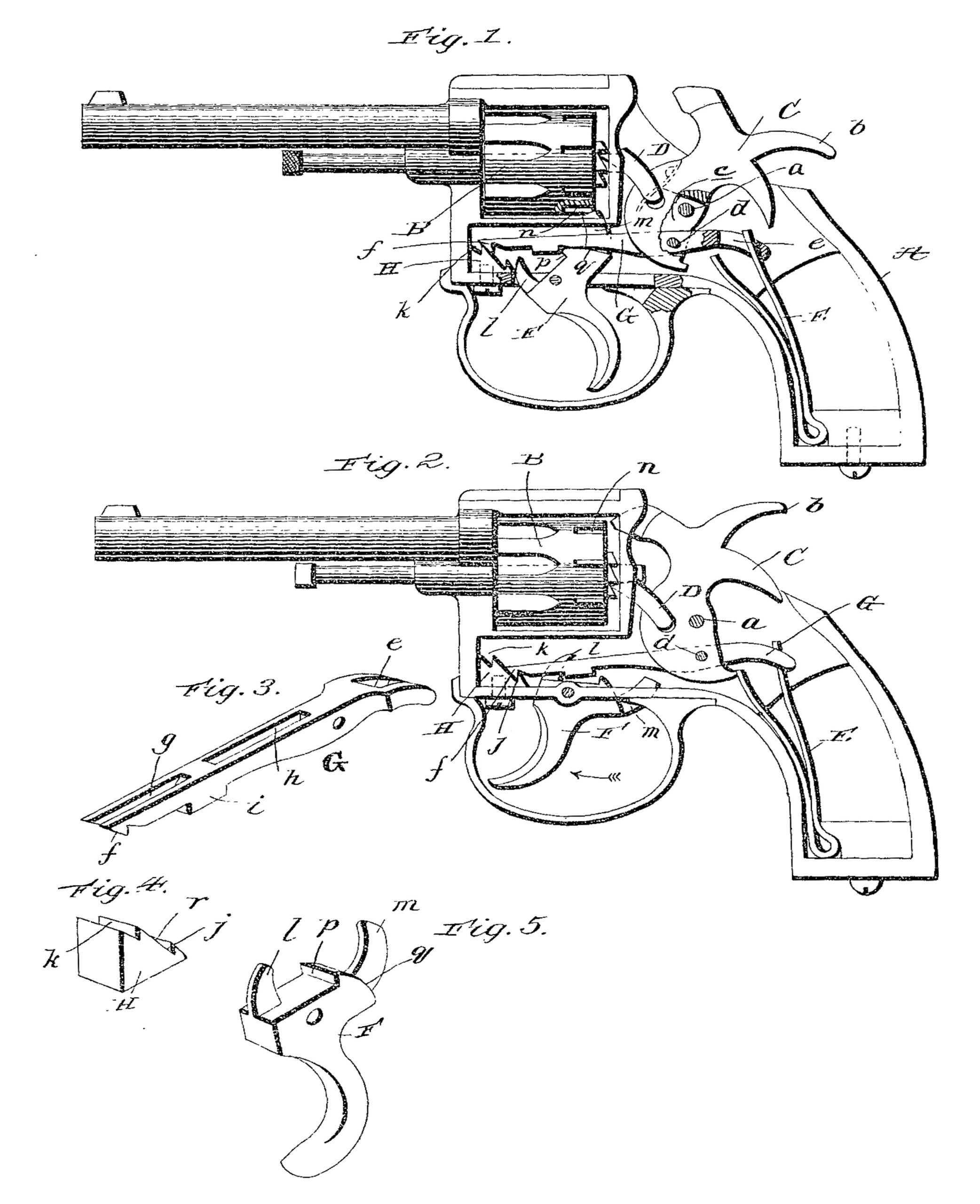
Figure 1 is a side elevation, partly in section, of a revolving firearm embodying my invention, the same being shown with the parts in the position they are caused to assume by a partial retraction of the trigger. Fig. 2 is a similar view with the parts in their normal position—that is to say, the position they assume when the latch is released from the trigger and the hammer is impelled against a cartridge. Fig. 3 is an enlarged perspective view of the late. Fig. 4 is a similar view of the keeper for the latch. Fig. 5 is an enlarged perspective view of the trigger.
In the said drawings similar letters designate corresponding parts in all of the several views, referring to which—
A is the frame of a revolving firearm; B, the revolving cylinder; C the hammer, fulcrumed at a and having the usual projections b to permit of its being cocked by the direct application of the thumb, and D the pivoted finger on the hanger for engaging as the hammer is raised with the teeth of the ratchet on the rear end of the cylinder to turn the same after the well-known manner.
When the invention is embodied in non-revolving firearms, the cylinder and finger will obviously be omitted.
E is the hammer-impelling spring; F, the trigger; G, the latch, and H the latch-keeper.
In the preferred embodiment of the invention the latch extends through an opening c in the hammer, to which it is pivotally connected at d, and is provided in rear of said hammer, and preferably at its rear end, with an eye e, receiving the spring E. At its forward end the latch is provided with a beveled toe f, designed to engage the keeper in a manner hereinafter described, and it is also provided with the bifurcation g at its forward end, the slot h at an intermediate point of its length, and the projection i at its under side between the bifurcation and slot, as shown.
The keeper H is fixed to the frame A in advance of the latch and is provided with a seat j, designed to receive the toe f of the latch when the hammer is in its normal position, (see Fig. 2,) and a seat k, designed to receive the said toe f when the hammer is cocked by the direct application of the thumb thereto, and its upper portion is moved to a position slightly beyond that shown in Fig. 1. With the toe of the latch arranged in either of the seats j h of the keeper forward movement of the hammer is precluded, and hence if the hammer is struck by any object or the firearm is dropped and the hammer strikes the ground no harm will result, since said hammer is effectually prevented from striking against the cartridge in the chamber of the cylinder presented to it.
The trigger F is pivoted or fulcrumed in the frame A at a point below the latch and is provided with a forward arm l, designed to work in the bifurcation g of the latch and guide the same in its vertical movements, and a rear arm m, designed to work through the slot h of the latch and into the seats n of the cylinder, so as to lock said cylinder against rotation at the time of firing. The said trigger is further provided with a shoulder p, designed to engage the rear side of the projection i on the latch G, and a cam-surface q in rear of the shoulder p, designed to act against the under side of the latch.
In addition to guiding the latch G in its vertical movements the arm l of the trigger serves to limit the movement of the trigger in the direction indicated by the arrow in Fig. 2, and thereby holds the shoulder p thereof in close proximity to the projection i of the latch. In consequence of this, when the trigger is drawn in the direction opposite to that indicated by arrow the shoulder p thereof will act immediately against the projection i of the latch and move said latch forwardly and through the medium of the same cock the hammer. This forward movement of the latch will, by reason or the beveled toe f engaging the beveled or forwardly-inclined surface r of the keeper, be attended by an upward movement of the forward end of the latch, which will raise the toe f out of the seat j. At this time the cam-surface q of the trigger will come into play and acting against the under side of the latch will raise the same, thereby disengaging the projection i from the shoulder p and releasing the latch and hammer and enabling the spring E to forcibly impel said hammer against the cartridge presented to it.
When the hammer is cocked by the direct application of the thumb to its portion b, its rearward movement is greater than when it is cocked through the medium of the trigger, and, in fact, is sufficiently great to move the toe f of the latch upwardly and forwardly into the upper seat k of the keeper. When the trigger is drawn to fire the firearm, cocked in the manner just described, the shoulder p of the trigger is idle; but the cam q, engaging the under side of the latch, lifts the toe thereof out of the seat k of the keeper, when the spring E, acting as before described, impels the hammer against the cartridge.
The latch not only serves to transmit motion from the trigger to the hammer when the trigger is retracted to cock and fire the firearm, but also to transmit motion from the hammer-impelling spring to the hammer, thus further simplifying the mechanism. It will be appreciated from the foregoing that a blow on the hammer of my improved firearm will not discharge the same and that this is an important advantage, since a very large proportion of the accidents with revolvers and other firearms arises from some unintentional shock to the hammer. It will also be observed that the utilization of the latch as a medium for transmitting motion from the trigger to the hammer and from the spring to the hammer is a material simplification of firearm mechanism and renders the mechanism as a whole very strong and durable and not liable to get out of order.
Having described my invention, what I claim, and desire to secure by Letters Patent, is—
1. In a firearm, the combination of a frame, a hammer, an endwise-movable safety-latch therefor, a hammer-impelling spring an immovable latch-keeper rigidly connected to the frame, and a trigger for disengaging the latch from the keeper, substantially as specified.
2. In a revolving firearm, the combination of a frame, a revolving cylinder, a hammer, means for rotating the cylinder incident to the rearward movement of the hammer, a hammer-impelling spring, a safety-latch for the hammer provided with an opening, a latch-keeper fixed to the frame and disposed below the cylinder, and a trigger arranged to disengage the latch from the keeper and having an arm arranged to pass through the opening of the safety-latch and coact with means on the cylinder to lock the same against rotation at the time of firing, substantially as specified.
3. In a firearm, the combination of a hammer, a hammer-impelling spring, a safety-latch connected with the hammer, a latch-keeper having two seats to receive the latch, and a trigger equipped to disengage the latch from the keeper and release said latch, substantially as specified.
4. In a firearm, the combination of a hammer, a hammer-impelling spring, a safety-latch connected with the hammer and having a beveled toe at its forward end and also having a shoulder at its under side, a latch-keeper disposed in advance of the latch and having lower and upper seats for the toe thereof an a forwardly-inclined surface between said seats, and a trigger having a shoulder to engage that of the latch and also having a cam, substantially as specified.
5. In a firearm, the combination of a hammer, a hammer-impelling spring, a latch having a shoulder at its under side and a bifurcation in advance of the shoulder, a latch-keeper, and a trigger having a shoulder to engage that of the latch and a cam to bear against the under side of the latch and also having an arm passing through the bifurcation of the latch, substantially as specified.
6. In a revolving firearm, the combination of a revolving cylinder, a hammer, means for. rotating the cylinder incident to the rearward movement of the hammer, a hammer-impelling spring, a safety-latch for the hammer having a slot, a latch-keeper, and a trigger arranged to disengage the latch from the keeper and having an arm arranged to pass through the slot of the latch and coact with means on the cylinder to lock the same against rotation at the time of firing, substantially as specified.
7. In a revolving firearm, the combination of a revolving cylinder, a hammer fulcrumed at an intermediate point, means for revolving the cylinder incident to backward movement of the hammer, a latch connected to the hammer below the fulcrum thereof and extending in front and rear of said hammer and having a shoulder at its under side and a slot in rear of the shoulder and also having its forward end bifurcated, a hammer-impelling spring engaging the latch in rear of the hammer, a latch-keeper, and a trigger disposed below the latch and having a shoulder and a cam and also having a forward arm passing through the bifurcation of the latch, and a rear arm arranged to pass through the slot in the latch and coact with means on the cylinder to lock the same against rotation at the time of firing, substantially as specified.
In testimony whereof I have hereunto set my hand in presence of two subscribing witnesses.
GEORGE W. CHANDLER.
Witnesses:
FRANK D. BLACKSTONE,
C. H. RAEDER.