
US 633734
UNITED STATES PATENT OFFICE.
JACOB RUPERTUS, OF PHILADELPHIA, PENNSYLVANIA.
LOCK FOR FIREARMS.
SPECIFICATION forming part of Letters Patent No. 633,734, dated September 26, 1899.
Application filed April 3, 1899. Serial No. 711,502. (No model.)
To all whom it may concern:
Be it known that I, JACOB RUPERTUS, a citizen of the United States, residing in the city and county of Philadelphia, in the State of Pennsylvania, have invented certain new and useful Improvements in Firearms, of which the following is a specification.
My improvements relate especially to the hammer and hammer controlling mechanism of fire arms, and it is my object to provide a self-cocking fire arm combining simplicity of parts with reliability in operation, and which shall be so constructed and arranged as to be especially secure against accidental discharge.
In the accompanying drawings I show, and herein I describe my improvements as employed in connection with a well-known type of revolver, provided with a hood which incloses and conceals the hammer.
In the accompanying drawings,
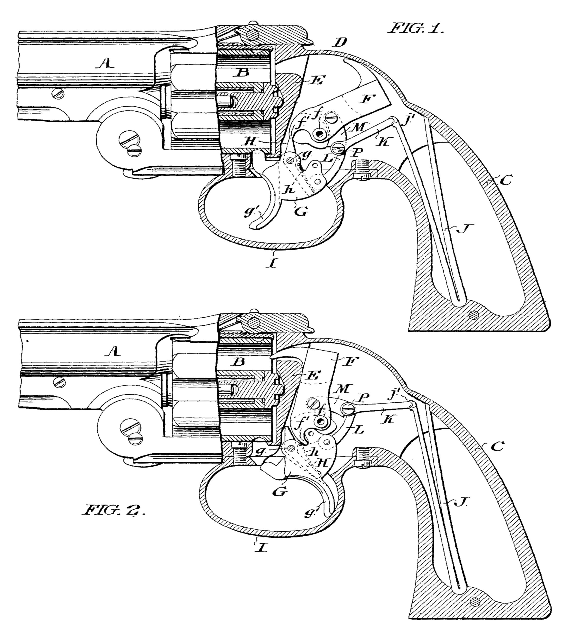
Figure 1 is a view in side elevation, partly in section, of a revolver embodying a good form of my invention, the parts being shown as occupying their normal position.
Figure 2 is a view similar to Figure 1, the parts being shown in the position they occupy at the moment of the discharge of a cartridge.
In the accompanying drawings,
A is the pistol barrel, B the revolving cartridge holder, C the stock, and D the hammer inclosing hood.
E is the transverse plate which closes the front of the lock chamber, provided with the usual hammer channel, as shown particularly in Figure 1, through which the nose of the descending hammer passes to encounter a cartridge in the cartridge holder disposed in line with said opening.
F is the hammer, the upper portion of which is, in the form illustrated in the drawings, suitably fashioned for operation within the hood-covered lock-chamber, which hammer is mounted upon and free for rotative oscillation with respect to a pivot f the respective extremities of which are housed in the side walls of said chamber.
The front portion of the lower end of the hammer is conveniently provided with a bearing shoulder f’, whereof hereinafter.
The trigger G is pivotally mounted for oscillation upon a pivot g, the respective extremities of which are housed in the side walls of the lock chamber, and is provided with a finger piece g’ of any usual form around which extends the usual metallic guard I.
H is a dog or pawl adapted to be tripped in the movement of the trigger.
Preferably the trigger is formed with a central dog recess extending vertically through its body and opening through its upper and lower edges respectively, and I prefer to locate the dog in this chamber and pivotally mount it upon the pivot g upon which the trigger is mounted, but independent of said trigger, with the result that said dog and trigger are capable of slight oscillation independently of each other, such independent oscillation ceasing, however, when said dog encounters the front or rear wall of the dog recess, or the spring h in front of said rear wall.
The upper end of the dog projects above the trigger, and is of such dimensions and so arranged as to be adapted to encounter the bearing shoulder f’ of the hammer as hereinafter more fully explained.
h is a small flat spring mounted in the rear portion of the dog recess, and bearing at times as to its free lower end against the dog, tends to force said dog into engagement with the bearing shoulder f’ when the parts are in appropriate position.
J is the main spring of the fire arm, conveniently mounted, in the form of fire arm I elect to illustrate, within the stock, in any preferred manner, and, in the preferred embodiment of my invention herein illustrated and described, provided with a link Ix, hereinafter termed the main-spring link, the outer end of which is seated in a suitable recess or socket in the free end of, or otherwise connected with, said main spring, and the inner end of which is pivotally connected with what I term the trigger link L, the lower end of which trigger link is pivotally connected to the rear portion of the body of the trigger.
The main spring link K and the trigger link L, connected by the pivot P, together constitute a toggle joint through which the main spring at all times, owing to its disposition and arrangement, exerts its force downward against the rear portion of the trigger and tends to throw said trigger forward into the position shown in Figure 1.
M is a hammer link, the front end of which is pivotally connected to the body of the hammer, and the rear end of which is pivotally connected to the connecting pivot P.
The operation of the apparatus will be readily understood.
In the normal position of the parts the hammer is up in the cocked position shown in Figure 1, and is maintained in such position by the stress or force of the main spring itself, transmitted through the links K and M, from which it results that only such force applied to the trigger as will overcome the force of said spring or change its direction of application will cause the descent of the hammer and the discharge of the fire arm; hence the weapon is thoroughly protected against accidental discharge by light fingering or jars or contact of such slight objects as would occasion the discharge of an ordinary fire arm.
As will be understood, the pressure of the main spring through the links K L is strong and constant and tends to maintain the trigger pressed forward to the limit of its movement.
To recapitulate: the force of the main spring exerted through said toggle K L referred to, downwardly against the trigger, not only serves to force the trigger forward to the limit of its movement, but also serves, by the engagement of the main spring link K with the hammer link M, to draw downwardly and backwardly upon said hammer and thereby to maintain said hammer in its open or cocked position.
The hammer thus maintained in its open or cocked position by the stress of the main spring, is also positively locked in such position by the dog hereinbefore described, the upper end of which is normally in contact with the bearing shoulder of said hammer.
When, however, it is desired to discharge the weapon, and rearward manual traction of sufficient force is exerted against the finger piece, said trigger will be caused to swing rearwardly with respect to its pivot,—without, however, occasioning at first any movement of the dog H,—and in such movement will, through the trigger link L, cause the manual pressure applied to the finger piece to be applied against the pivot pin P and through said pivot pin, and the hammer link M, and main spring link K, against the hammer and main spring.
Inasmuch as the hammer is for the time being, locked by the dog against forward movement, the main spring yields and recoils under the manual pressure, the trigger link, pivot pin, spring link, and hammer link, all rising as said spring yields, until said pivot pin is slightly above a line intersecting the pivot f of the hammer and the point of connection j’ between the main spring and main spring link.
So soon as the parts are in this last described position, a portion of the strength or thrust of the main spring becomes directed, through the main spring link and the hammer link, against the hammer, and will tend to force said hammer down; at the same time the front wall of the dog recess,—or other device intended for the tripping of the dog,— will in the rearward movement of the trigger encounter the lower end of the dog and occasion its rearward movement, thereby, of course, throwing its upper end forward and clear of the bearing shoulder of the hammer.
As soon as by the tripping of the dog the shoulder of the hammer is released, said hammer is, by that portion of the force of the main spring which has been diverted, so to speak, from its normal application directly against the trigger, driven strongly and abruptly forward, to encounter and occasion the explosion of the charge within the cartridge.
After such discharge, as soon as the manual pressure is removed from the finger piece, the main spring, which has not ceased to bear more strongly against the trigger than against the hammer, will, by pressure against said trigger, drive said trigger forward to its normal position and at the same time through the hammer link draw said hammer backward to its open position.
This action is due to the fact that at the time of the release of the manual pressure against the finger piece, the parts are in the position shown in Figure 2, with the main spring exerting force through the hammer link against the hammer and through the trigger link against the trigger.
Inasmuch as the hammer cannot further yield or move farther forward, while the trigger can very readily do so, said trigger will under the stress of the spring immediately begin to move forward.
Very slight movement forward of the trigger lowers the pivot pin P so that it falls below an imaginary line passing through the pivot of the hammer and the point of junction of the main spring and its link,—with the result that the two links K M assume a more angular relationship and the stress of the mainspring not only ceases to press the hammer forward but acts to draw it rearwardly.
At the moment the hammer reaches its open or cocked position and the trigger almost reaches its normal forward position, the rear wall of the dog recess or the spring h disposed in front thereof,—encounters the lower end of said dog, and, moving it forward, occasions the rearward movement of its projecting upper end into locking engagement with the shoulder f’ of the hammer.
The trigger is of course to be equipped with the usual devices through the operation of which the rotation of the cartridge cylinder is occasioned.
Having thus described my invention, I claim and desire to secure by Letters Patent—
1. In a fire arm, a trigger, a pivoted hammer,and a mainspring, a connection between said spring and said trigger through which said spring tends to constantly force said trigger forward, and a movable connection between said spring and said hammer through which when said connection is in normal position and the trigger is forward said spring holds said hammer in open position, but through which when moved or elevated by the rearward movement of the trigger said spring forces said hammer to closed position, substantially as set forth.
2. In a fire arm, a trigger, a pivoted hammer, and a mainspring, a connection between said spring and said trigger through which said spring tends to constantly force said trigger forward, and a movable connection between said spring and said hammer through which when said connection is in normal position and the trigger is forward said spring holds said hammer in open position, but through which when moved or elevated by the rearward movement of the trigger said spring forces said hammer to closed position, a dog which locks the hammer in open position, and means for tripping said dog as the trigger is moved rearwardly, substantially as set forth.
3. In a fire arm, in combination, a trigger, a hammer, a main spring, means, structurally independent of the main spring, and acted on by said main spring through which the pressure of said spring is applied to the hammer, and means, structurally independent of said spring, and acted on by said spring through which the pressure of said spring is applied to the trigger, substantially as set forth.
4. In a fire arm,in combination, a hammer, a trigger, a main spring, mechanism connective of said main spring and said trigger, and a link which connects said hammer to said mechanism, substantially as set forth.
5. In a fire arm, in combination, a pivotally mounted hammer, a trigger, a main spring, a main spring connecting mechanism connective of said main spring and said trigger, and a link which connects said hammer to said main-spring-connecting mechanism, the point of junction of said link with said mechanism being carried in the operation of the fire arm alternately above and below a line drawn from the pivot of the hammer to the upper end of said connecting mechanism, substantially as set forth.
6. In a fire-arm, in combination, a mainspring, a hammer, a trigger, a link connected with said trigger, means for applying the pressure of the main spring against said link, a link connected to said hammer, and means for applying the pressure of the main spring against said link, substantially as set forth.
7. In combination, a trigger, a hammer, and a main spring, a series of three links each connected to or engaged with one of said devices as to its outer end and all as to their inner ends connected to a common movable pivot, substantially as set forth.
8. In combination, a trigger, a hammer, and a.main spring, a series of three links each connected to or engaged with one of said devices as to its outer end and all as to their inner ends connected to a common pivot, which pivot in the manipulation of the trigger is moved to different positions so as to distribute the pressure of the main spring in varying degree against said trigger and hammer, substantially as set forth.
9. In combination, the trigger having a dog recess, the hammer provided with a shoulder, a dog mounted in the dog recess of the trigger and adapted for engagement with the shoulder of the hammer, a pivot upon which the trigger and dog are mounted free for slight movement independent of each other, a main spring, a main spring link, a trigger link, and a hammer link, and a pivot which connects the meeting ends of said three links, substantially as set forth.
In testimony that I claim the foregoing as my invention have hereunto signed my name this 25th day of March, A. D. 1899.
JACOB RUPERTUS.
In presence of—
F. NORMAN DIXON,
THOS. K. LANCASTER.