
US 609233
UNITED STATES PATENT OFFICE.
LEWIS T. HOUGHTON, OF WORCESTER, MASSACHUSETTS.
SAFETY DEVICE FOR FIREARMS.
SPECIFICATION forming part of Letters Patent No. 609,233, dated August 16, 1898.
Application filed February 19, 1898. Serial No. 670,881. (No model.)
To all whom it may concern:
Be it known that I, LEWIS T. HOUGHTON, a citizen of the United States, residing at Worcester, in the county of Worcester and State of Massachusetts, have invented a new and useful Improvement in Safety Devices for Firearms, of which the following, together with the accompanying drawings, is a specification sufficiently full, clear, and exact to enable persons skilled in the art to which this invention appertains to make and use the same.
This invention relates to a novel and peculiar construction, arrangement, and mode of operation of the safety device for preventing the hammer striking the cartridge excepting when the lock mechanism is normally actuated by pulling the trigger. Different combinations of mechanism have been employed for safety purposes previous to my invention, and I do not include the broad idea of a trigger-operated safety device as of my invention.
The objects of my invention are the improvement of this class of mechanism and to provide for the purpose named a simple, efficient, and desirable means which can be economically manufactured and practically applied to firearms of various kinds, more especially as an adjunct in the structure of the ordinary double-action-revolver lock mechanism and for rendering the arm more reliable and safe. I attain these objects by mechanism embodying the peculiar structure and mode of operation illustrated in the drawings, wherein—
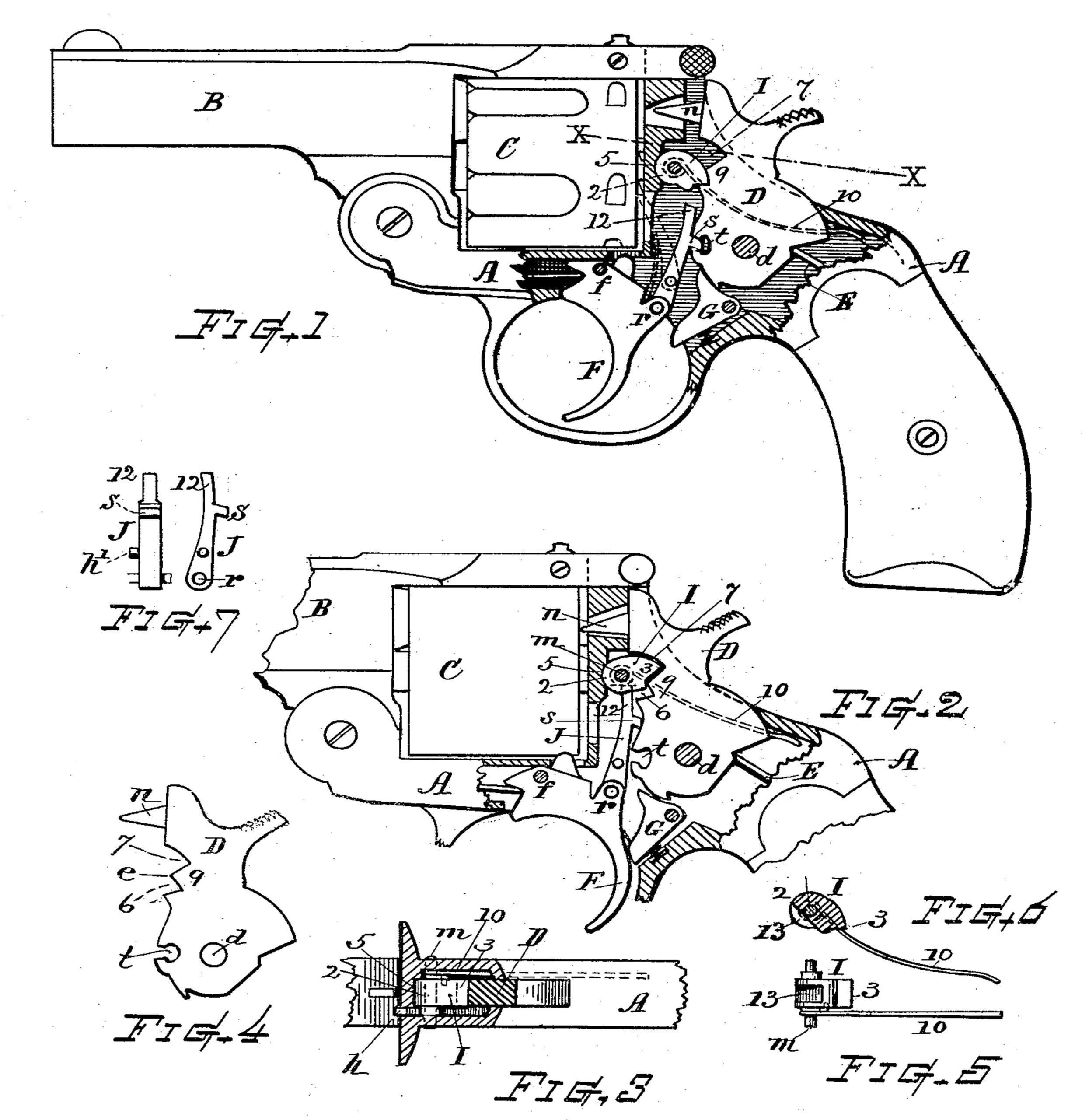
Figure 1 is a side view, partly in section, of my improved safety mechanism as applied to a double-action revolver with the parts at position of safety. Fig. 2 is a similar view showing the parts at position of firing. Fig. 3 is a horizontal section at line X X on Fig. 1. Fig. 4 is a side view of the hammer separately. Fig. 5 is a bottom view of the safety-block. Fig. 6 is a vertical section of the same, and Fig. 7 shows a rear view and side view of the lifter-pawl having the extension-finger.
Referring to parts, A denotes the frame; B, the barrel; C, the cylinder; D, the hammer, pivoted at d; F, the trigger, pivoted at f; G,the sear; E, the mainspring; J, the hammer-lifting pawl, and I the improved safety-block. The parts which are not herein specifically described in detail may be of any well-known or suitable construction.
The safety-block I consists of a small piece of metal having a rounded front end 2 and a tapered wedge-shaped or angle-edged rear end 3. Said block is disposed, as shown, within the lock-chamber in front of the hammer-breast and is horizontally pivoted within the frame by the pin m, so that its rear part or angular end portion 3 can swing up and down within a limited arc, acting as an adjustable dog or stop for intercepting the hammer. The frame is best made with a seating-surface at 5, and the rounded end 2 of the safety-block is fitted to bear against and rock on said seat, thus affording support for the block against the solid frame and relieving the pivot-pin m from strain and shock.
In the front edge or breast of the hammer, below its face or striker-point n, I provide two transverse indents, recesses, or notches 6 and 7, having between them a guard or wedge-shaped lug 9, presenting a sharp angular edge c, Fig. 4, disposed at such position that the angular end 3 of the safety-block I can pass below or above said lug, accordingly as said block is swung downward or upward. One of the recesses is formed of a dimension for the interception of the hammer, and the other is formed for the free reception of the block without interception of the hammer when the end of the safety-block is in line with such recess and the hammer swings forward.
A suitable spring 10 is combined with the safety-block, which spring normally acts to swing the end of the safety-block to its depressed position, so that it will enter the lower notch 6 in the hammer-front.
The lifter-pawl J, which is pivoted to the trigger-head at r, is in its general structure and operation of well-known, character, having the detent s, that engages the tumbler-nick t for throwing back the hammer; but in my invention said lifter-pawl is provided with an extension or finger 12, adapted for striking the under part of the pivoted safety-block I and elevating its rear end into alignment with the upper notch 7 in the hammer-breast.
The under rear part of the safety-block is best cut away, as shown at 13, Figs. 5 and 6, so that the finger 12 can swing forward with the throw-off movement of the pawl when the detent s escapes from the nick l.
In any instance where it is desired to employ this improved safety-block in firearms other than “double-action” revolvers the finger 12 or means for raising the swinging block I can be made as a pawl h’, similar to that shown in Fig. 7, but without the detent s thereon.
The operation is as follows: At any forward stroke of the hammer, when the rear end of the safety-block I is at such position that the knife-edge of the lug 9 passes above the rear end angle 3 of the safety-block, the end of said safety-block enters the lower notch 6, and the forward movement of the hammer is arrested by said block before the hammer-face or its striker-point n reaches the position of impingement on the cartridge, thus preventing an explosive discharge; but when the rear end of the safety-block I is swung upward, so that the edge of the lug 9 passes below the rear end 3 of the safety-block, then the end of the safety-block passes into the upper notch or recess 7, which is of sufficient dimension for its free reception, and the hammer is permitted to fall to the full extent of its stroke for effecting the explosive discharge of the cartridge.
The end 3 of the block I is normally maintained at depressed position and is only raised when the trigger is drawn back nearly or quite to the throw-off position. Consequently any accidental movement of the hammer will be intercepted by the safety-block catching in the notch 6, while at the regular firing operation the trigger action and finger 12 will swing the block so its end will avoid contact with the hammer by reason of the larger notch 7. The V-shaped notches 6 and 7 prevent the end of the swinging block from throwing out of position when the hammer falls thereon. The lower notch affords contact-surfaces for a positive and solid contact in the interception of the hammer movement.
By making the safety-block as shown and pivoting it in the frame to swing up and down at its rear end and forming the hammer with the angle-edged lug 9 and upper and lower recesses at the breast thereof a very simple and efficient safety mechanism is produced. The angled meeting edges on the parts avoid liability of an undetermined contact and sharply defines the limit between the positions for normal discharge and that at which the device stands for safety, thus rendering the improved construction very desirable and useful for the purpose intended.
I do not broadly claim, irrespective of construction, the introduction of a safety-stop between the hammer and frame in a firearm, as I am aware that a stop of different structure and operation has heretofore been devised for such purpose.
What I claim as of my invention, and desire to secure by Letters Patent, is—
1. The combination with the hammer, the trigger, and the lifter-pawl, of a safety block or dog pivoted within the frame adjacent to the recoil-plate, its rear end adapted to swing up and down and to meet a recess and contact-surface at the breast of the hammer respectively above and below a guard-lug thereon, a spring that normally depresses the rear end of said swinging block, and a finger or lifter-pawl actuated by the trigger, for swinging upward the end of said safety-block at the final limit of the trigger action, substantially as set forth.
2. In combination with the hammer having its breast provided with the upper and lower recesses or notches 6 and 7, and the intervening angle-edged lug 9, the safety-block I pivoted in the frame, its rearwardly-projecting end adapted to swing above or below said lug, a spring that normally depresses the end of said safety-block, and means substantially as described for elevating said end when the trigger is drawn back.
3. In a firearm, in combination as described, the frame provided with the seating-surface 5, the safety-block I pivotally confined in the frame by a pin m, and having a rounded end acting against said seat, and an angle-edged rear end movable up and down by swinging action, a spring normally swinging said block in one direction, the pivoted hammer having the front angle-edged lug 9 with recesses above and below said lug, one of said recesses formed to effect interception of the hammer by contact with said block, and the other recess formed for receiving the end of the block without interception of the hammer, the lifter-pawl pivoted to the trigger-head and having the extension-finger 12 for operating said safety-block, substantially as set forth.
4. The pivoted upwardly and downwardly swinging safety-block having its under front portion cut away or recessed, as at 13, in combination with the hammer, and the hammer-lifting pawl carrying the detent s and provided with the extended finger 12, for the purpose set forth.
Witness my hand this 17th day of February, 1898.
LEWIS T. HOUGHTON.
Witnesses:
CHAS. H. BURLEIGH,
SIMEON E. KING.