
US 557814
UNITED STATES PATENT OFFICE.
GILBERT H. HARRINGTON AND WILLIAM A. RICHARDSON, OF WORCESTER, MASSACHUSETTS, ASSIGNORS TO ARMS COMPANY, OF SAME PLACE.
THE WARRINGTON & RICHARDSON EJECTOR MECHANISM FOR REVOLVERS.
SPECIFICATION forming part of Letters Patent No. 557,814, dated April 7, 1896.
Application filed December 22, 1894. Serial No. 632,682. (Model.)
To all whom it may concern:
Be it known that we, GILBERT H. HARRINGTON and WILLIAM A. RICHARDSON, of the city and county of Worcester, State of Massachusetts, have invented certain new and useful Improvements in Revolvers; and we do hereby declare that the following is a full, clear, and exact description thereof, reference being had to the accompanying drawings, forming a part of this specification, and in which–
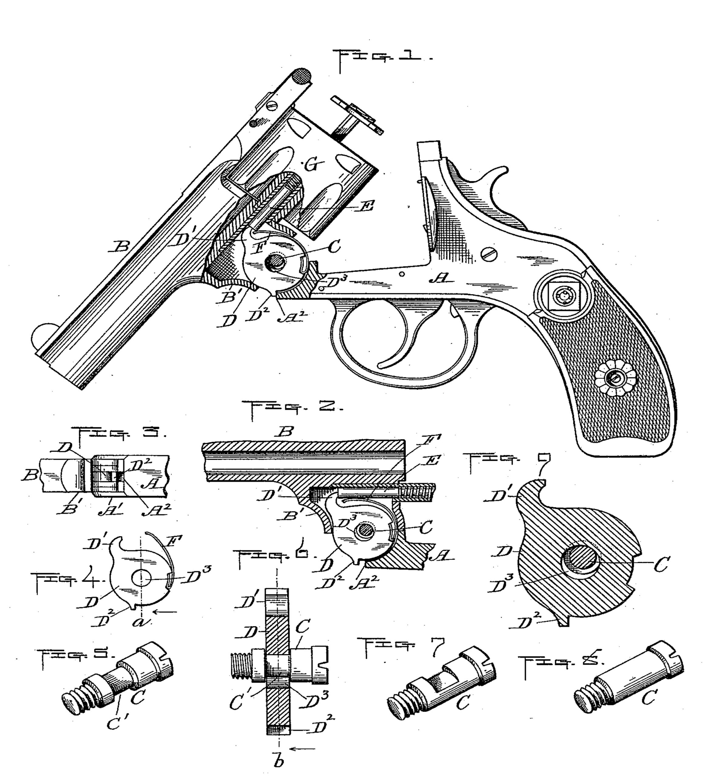
Figure 1 represents a side view of a revolver with the front end unlocked and swung down as in practice in the operation of extracting the cartridges or shells from the cylinder, part of the side being broken away to illustrate our improvements hereinafter described. Fig. 2 represents a vertical section of that portion of the revolver to which our said invention relates, showing the parts in their normal positions prior to unlocking and swinging down the frontend, as aforesaid. Fig. 5 is a bottom edge view of the parts shown in Fig. 2. Fig. 4 is a detached view of the extractor-lifter and its spring. Fig. 5 is an enlarged perspective view of our improved pivot-screw or axis-pin, which will be hereinafter described. Fig. 6 is a section taken at the point indicated by line a in Fig. 4, with the pivot-screw or axis-pin shown in side view in the position which it occupies in the extractor-lifter when the parts are fitted in place in the revolver. Figs. 7 and 8 are perspective views of two modifications in the construction of the pivot-screw or axis-pin, which will be hereinafter described; and Fig. 9 is a section through the extractor-lifter and pivot-screw or axis-pin, taken at the point indicated by line b in Fig. 6.
Our invention consists, in brief, of combining the frame, barrel, spring, extractor-pin, and extractor-lifter, provided with a suitable actuating-spring and a substantially round transverse opening therethrough to receive the pivot-screw or axis-pin, with a pivot-screw or axis-pin whose transverse or cross diameter at its point of contact with the extractor-lifter, when fitted in the round opening thereof, is enough smaller than said round opening to admit of the usual lateral movements of said extractor-lifter, as will be hereinafter more fully set forth.
To enable others skilled in the art to which our invention appertains to better understand the nature and purpose thereof, we will now proceed to describe it more in detail.
Referring to the drawings, A represents the revolver-frame, having the bearing A’ at its forward end, to which the base B’ of barrel B is pivoted by means of our improved screw or axis-pin C. D is the extractor-lifter, consisting of a circular disk having a hook D’, adapted to engage with the inner end of the spring, extractor-pin E, and an ear or projection D2, adapted to engage with the end A2 of frame A to hold said disk from turning when the barrel is swung down, as shown in Fig. 1 of the drawings, to extract the empty cartridge-shells.
F is a flat spring attached to the inner edge or periphery of the disk at a convenient point between its lifter-hook D’ and projection D2. Its free end curves up over the disk toward its hook and bears at its outer side against the underside of the extractor-pin for the purpose of producing a constant friction thereon to hold it and the cylinder G, to which it is attached, from turning too freely when the cylinder is not locked, or, in other words, when the arm is in its normal position ready for raising the hammer preparatory to firing. Said spring, it is obvious, serves the double purpose of exerting a constant friction upon the extractor-pin, as aforesaid, and also to shift the extractor-lifter forward and downward, so that its projection will always engage with and hold against the projection A2 on frame A to lock said extractor-lifter in the usual operation of extracting the cartridge-shells. To admit of said shifting movements of the extractor-lifter, the circular transverse opening D3 in the latter is made larger in diameter all around than the diameter of that part of the pivot-screw or axis-pin in said opening, so as to allow the spring F to shift said lifter into the required position for its projection D2 to engage the end A2 of the frame A, as aforesaid.
While we prefer to make the opening D3 in the extractor-lifter D round, as shown in the drawings, it will be understood that this opening need not necessarily be mathematically round to permit of the shifting movement above described, so long as it is larger in diameter all around than the diameter of that part of the pivot-screw or axis-pin therein.
The pivot-screw or axis-pin may be made of various shapes to pass through the extractor lifter and at the same time admit of the aforesaid shifting movement of said lifter thereon, and we therefore do not limit ourselves to any special shape so long as the principle described is carried out—viz., of making that portion of said screw or axis-pin which comes within the limit of the two sides of the lifter around its opening of less transverse diameter than the size of said opening.
In Figs. 1, 2, 5, 6, and 9 we have shown the pivot-screw or axis-pin with an annular groove C’ formed therein at the above-mentioned point, the shoulders at each side of said groove coming at each side of said opening, while in Fig. 7 we have shown a pivot-screw or axis-pin with said groove extended only part way around the periphery thereof, in practice said grooved portion being arranged to come in line with the line of motion of the extractor-lifter, so as to permit its spring to force it forward and downward, as previously specified.
In Fig. 8 we have shown a plain pivot-screw or axis-pin of equal diameter of shank, which in practice is made of the proper transverse diameter to carry out substantially the same proportion in size to the opening in the lifter as the diameter of the grooved portion of the annular grooved screw or axis-pin is to said opening.
It will at once be apparent that the same result may be accomplished by the use of any of said constructions in connection with a round opening in the extractor-lifter, and we therefore do not limit ourselves to any special shape of pivot-screw or axis-pin in carrying out said principle.
One of the advantages which we claim of using a round opening in the extractor-lifter and a pivot-screw or axis-pin constructed as described is that it practically does away with the extreme accuracy of adjustment in making and fitting the parts (especially when the annular grooved or plain pivot-screws or axis-pins are used) which has heretofore been considered necessary by the old constructions, thereby materially reducing the cost of manufacture and at the same time enhancing the value of the arm.
Another advantageous feature which we claim is that by the use of a round instead of the customary oblong or similar-shaped openings the extractor-lifter has a free circular shifting movement on the pivot-screw or axis pin as it is turned forward and downward, and therefore automatically assumes, without friction, any position it is forced into by its spring and the action of operating the arm. This and the advantage first described we claim are essential and important features.
Having now described our said invention, what we claim as new, and desire to secure by Letters Patent, is—
In a revolving firearm, the combination with the frame, barrel, and extractor-pin, of an extractor-lifter spring, a pivot-screw or axis-pin, and an extractor-lifter having a round transverse opening through which said pivot-screw or axis-pin passes and which opening is larger in diameter than the diameter of that part of said pivot-screw or axis pin in said opening, to permit of a free circular shifting movement of said extractor-lifter, as well as a forward and downward movement thereof, substantially as and for the purposes set forth.
GILBERT H. HARRINGTON.
WILLIAM A. RICHARDSON.
Witnesses:
WALTER B. NOURSE,
ALBERT A. BARKER.