
US 554058
UNITED STATES PATENT OFFICE.
CHARLES FOEHL, OF PHILADELPHIA, PENNSYLVANIA, ASSIGNOR OF ONE-HALF TO HENRY RUHLAND, OF SAME PLACE.
CYLINDER-STOP FOR REVOLVERS.
SPECIFICATION Forming part of Letters Patent No. 554,058, dated February 4, 1896.
Application filed July 10, 1895. Serial No. 555,457. (No model.)
To all whom it may concern:
Be it known that I, CHARLES FOEHL, a citizen of the United States, residing in the city and county of Philadelphia, State of Pennsylvania, have invented a new and useful Improvement in Revolvers, which improvement is fully set forth in the following specification and accompanying drawings.
My invention consists of a revolver or firearm provided with novel means for locking the revolving cylinder of the same alternately while said chamber is at rest and just in advance of firing, as will be hereinafter set forth.
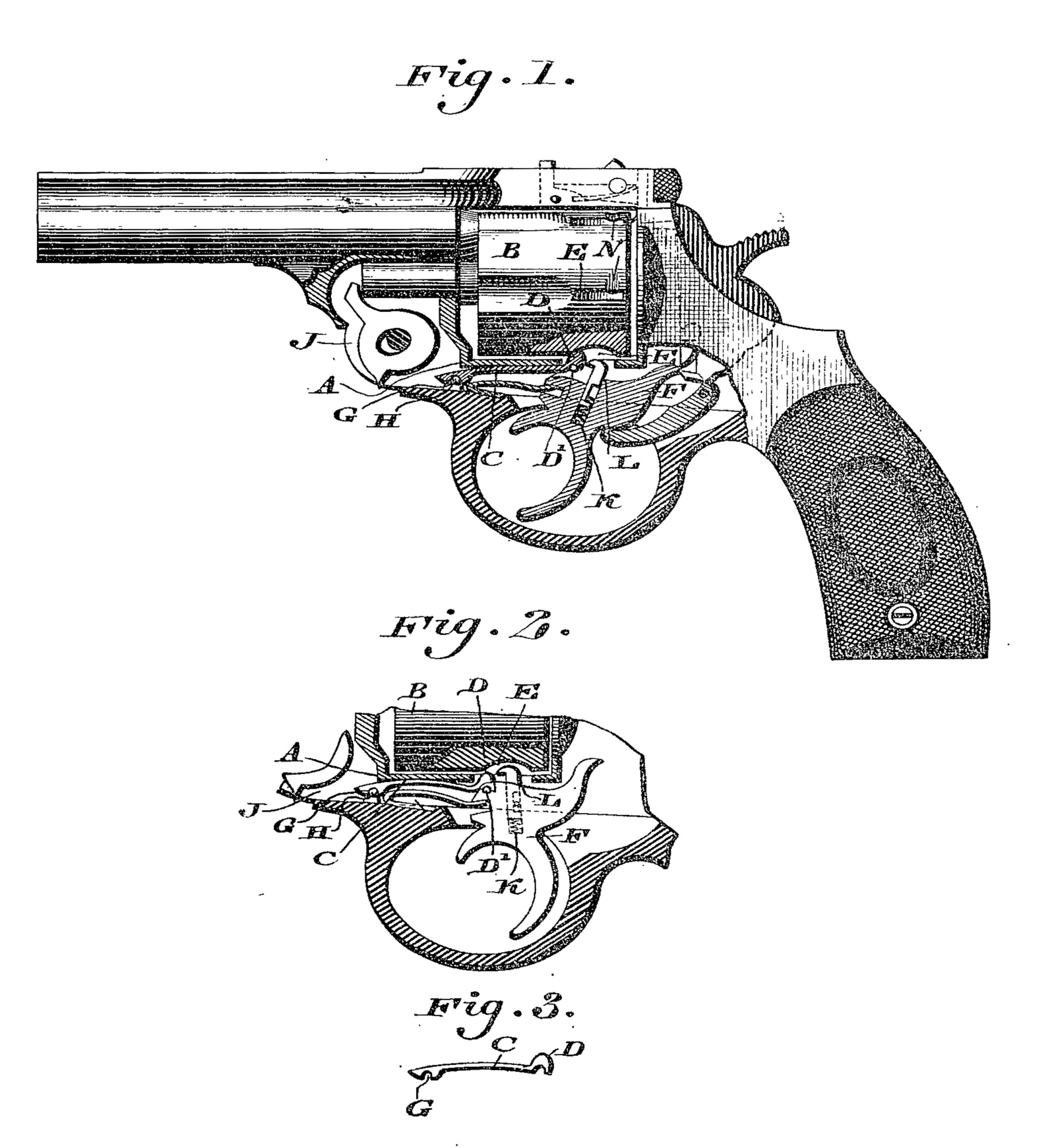
Figure.1 represents a partial side elevation and partial section of a revolver embodying my invention. Fig. 2 represents a section of a portion, showing certain members in different positions from that shown in Fig. 1.
Similar letters of reference indicate corresponding parts in the two figures.
Referring to the drawings, A designates the frame of a revolver or firearm below the rotary cylinder B, and C designates a spring-catch, the rear end of which has the head D, which is adapted to enter the adjacent recess E in the outer peripheral wall of said cylinder, said head being also adapted to rest on the pin D’ on the upper end of the forward part of the trigger F, so as to be raised by the latter, the tendency of said catch being to lower when the trigger is pulled. The forward end of the catch has on its under side the notch or recess G, the wall of which is seated on the pin H, the latter being connected with the portion J of the frame A, the body of the spring pearing in part upwardly against the frame A.
In the trigger is a vertical recess K, which is occupied by the shank of a spring-pressed bolt or catch L, whose head is adapted to enter a portion of either of the recesses E in the cylinder B when the trigger is pulled, as will be hereinafter more fully explained.
In the outer peripheral wall of the cylinder B are recesses N, which extend around the same at a right angle to the recesses K, so that when the catch L rises and the cylinder rotates the head of said catch enters the approaching recess N, and is thus guided into the recess E.
In order to seat the head of the catch C on the trigger and prevent lateral motions thereof, the front end of the trigger is formed with a small recess to receive said head.
The operation is as follows: When the trigger is in its normal position, the catch C is held elevated by the same, and its head D occupies a portion of the adjacent recess E, and thereby locks the cylinder and prevents rotation of the same. (See Fig. 1.) Now as the rear portion of the trigger is down or lowered, as most plainly shown in Fig. 1, the catch L is removed from the recess E and remains inoperative. When, however, the pistol or revolver is to be discharged and the trigger drawn back, the pin D’ lowers and the catch C, previously bent upwardly, owing to its springy nature, also lowers, and causes its head to withdraw from the recess E, whereby the cylinder is unlocked. The cylinder rotates as usual, and as the rear end of the trigger rises the catch L is raised and enters the adjacent recess N, which has advanced toward it, and is guided by the same to the adjacent recess E which it then occupies, (see Fig. 2,) whereby the cylinder is locked by said catch L, this occurring just in advance of the firing or discharge, and continuing until the firing is accomplished. The trigger now returns to its first position, whereby the catch L lowers and the cylinder is unlocked, but as the pin D’ rises, due to the ascent of the front end of the trigger, the head of the catch C is forced into the recess E just above it, thus again locking the cylinder and preventing rotation of the same until the trigger is again pulled back, when the operations hereinbefore described are repeated.
When the side plate of the revolver is removed, the catch C may be readily removed when broken, it being readily replaced by a new piece, which may have the groove or recess G slipped over the pin H, thus restoring the catch in position.
Having thus described my invention, what I claim as new, and desire to secure by Letters Patent is–
1. In a revolver, the cylinder provided with recesses around the same, the trigger having the catch L therein, the frame formed with the pin H, and the catch C in said frame, said catches being adapted to alternately enter either of the recesses of the cylinder, said catch C having on its under side the recess G, which is seated on said pin H, substantially as described.
2. In a revolver, a cylinder having recesses around the same, and catches adapted to alternately enter said recesses, one of the catches being in the frame of the revolver, and the other catch being in the trigger, the catch in the frame having recesses in its heel and head ends on the under side thereof, and said frame and trigger haying pins thereon, on which said recesses are seated substantially as described.
CHARLES FOEHL.
Witnesses:
JOHN A. WIEDERSHEIM,
R. H. GRAESER.