
US 584698
UNITED STATES PATENT OFFICE.
JOHN L. MURPHY AND DANIEL J. MANNING, OF SPRINGFIELD, MASSACHUSETTS.
REVOLVER.
SPECIFICATION forming part of Letters Patent No. 584,698, dated June 15, 1897.
Application filed November 4, 1896. Serial No. 611,071. (No model.)
To all whom it may concern:
Be it known that we, JOHN L. MURPHY and DANIEL J. MANNING, citizens of the United States of America, and residents of Springfield, in the county of Hampden and State of Massachusetts, have invented certain new and useful Improvements in Revolving Firearms, of which the following is a specification.
This invention relates to improvements in revolving firearms and is especially applicable to the system of the well-known Colt’s double-action revolver, in which the cylinder swings transversely to open and close and which is confined and released by a catch having a longitudinal-sliding motion, which catch engages in a socket centrally in the rear end of the cylinder, or, more strictly speaking, in the ejector, which to all intents and purposes, so far as this invention is concerned, may be regarded as a part or fixture of the cylinder.
The primary object of the invention is to provide mechanism of improved construction whereby when the arm is cocked it becomes impossible to move the cylinder either in or out until the hammer has gone way down, or in fact, in this class of revolvers having a rebounding action, until the hammer has reached its position of rest. The improved mechanism also contemplates simplicity, ease and cheapness of construction, directness of action, and a compactness in the arrangement of the parts and a rendering of the arm at the Jock mechanism the better proof against the entrance thereinto of dirt and foreign substances; and the invention consists in the combination, with the longitudinally – movable cylinder-catch, of the hammer formed or provided with a projecting member and having at its edge toward the catch a less prominent portion, and being so mounted that when it is down its less prominent portion being behind the catch leaves the latter free to be moved, and when cocked its said projecting member is brought into a position to obstruct the movement of the catch. Preferably the projecting member has a form, as hereinafter described, whereby the cylinder-catch becomes immovable immediately the hammer has commenced to move toward cock, or, in fact, while at any position except that of its rest or “down.”
The improvements are applicable on revolving firearms of the class referred to already constructed, being susceptible of easy application with but a slight adaptation and interchange, or may be embodied as an integral part of the hammer, as would be preferable in newly-constructed arms.
The improvements are illustrated in the accompanying drawings and hereinafter described in conjunction therewith.
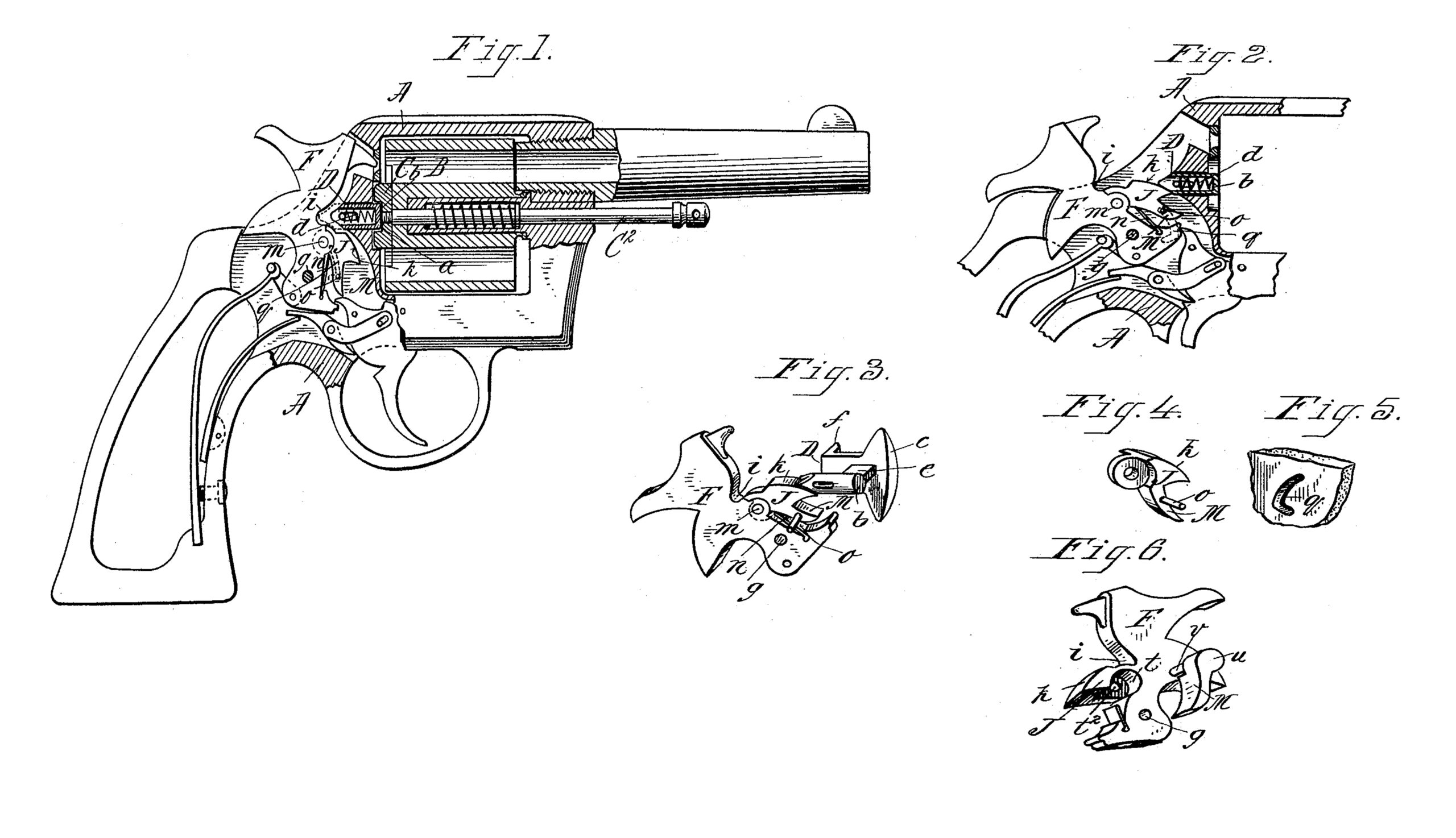
In the drawings, Figure 1 is a side elevation and partial central longitudinal section of a Colt’s revolver having a rebounding-hammer mechanism, the hammer being shown as down or in its position of rest and the safety-catch free to be moved to permit the cylinder to open sidewise in the manner common and well known in this class of arm. Fig. 2 is a substantially similar view to Fig. 1, but showing the hammer at cock and the cylinder-catch locked against movement. Fig. 3 is a representation in perspective of the relative positions of the cocked hammer and cylinder-catch locked against movement thereby: Fig. 4 is a perspective view of the member which is provided as a pivoted attachment to the hammer and which serves both as the cylinder-catch-locking projection and as the ‘‘strut” in the rebounding action. Fig. 5 is a view showing a groove or slot in the side plate or side of the frame in which a projecting pin on the aforesaid pivotally-attached member of the hammer courses as the hammer is swang and which serves a purpose hereinafter explained. Fig. 6 is a perspective view in which the hammer is shown as having its cylinder catch-obstructing member formed as an integral projecting part thereof, this view also showing the separately-formed strut and indicating the manner of its connection with the hammer.
In the drawings, A represents the frame of the arm apertured for the cylinder B, which is understood as adapted to swing transversely into and out from the aperture in the frame, as well known in the Colt’s revolver. The cylinder has fitted therein the ejector C, operated by the rod C2 against its spring, and the ejector has centrally at its rear end the socket a, in which the forward end b of the cylinder-catch D engages. The cylinder-catch, as usual, is movable longitudinally, being normally pressed forward by its spring d, and it has, carried by the lateral arm e, the thumb-lug f and the projection c, which is impinged against by the cylinder for a slight endwise movement of the catch as the cylinder is swung.
F represents the hammer pivotally mounted to swing within the frame behind the cylinder and cylinder-catch on the pivot-pin or screw at g. The hammer has its forward edge portion i milled out or recessed, so that when the hammer is in its down position (seen in Fig. 1) this recess is behind the cylinder-catch, leaving sufficient space between this so-formed front portion of the hammer and the rear of the catch, whereby the catch is left free to be moved to permit the cylinder to be released.
J represents the projecting member of the hammer below the receded portion i, which when the hammer is down is below and out of the way of the cylinder-catch, but which, essentially, when the hammer is at cock has its position behind and against the catch, whereby then the catch cannot be moved. This projecting member of the hammer is preferably formed with a suitably-elongated edge i, concentric with pivot g, that about as soon as the hammer is swung upwardly in any extent a portion of such edge k is brought into its obstructing position closely behind the catch.
M represents the strut, comprising part of the rebounding action not necessary to here describe, being well known. Inasmuch as large numbers of Colt’s revolvers are now made on which it is thought desirable to apply the present improved safety-stop for the cylinder-catch, it becomes advantageous to construct the part constituting the projection J integrally with the strut (which strut necessarily is pivotally connected to and carried by the hammer) and to pivot this strut and stop to the hammer at m, all as seen in Figs. 1, 2, and 3. The spring n is here applied in the usual way between the hammer and strut. The strut has the laterally-projecting pin o, which, as the strut is moved, as carried by the hammer, courses in the curved slot q in the side plate of or for the frame. When the hammer is swung back and the part J is behind the cylinder-catch D, any pressure rearwardly by the said catch will be without effect to cause the part J to recede, by swinging downwardly and rearwardly, by reason of the obstructing action of the pin o against the wall of the slot q.
For newly-constructed revolvers having a cylinder-catch substantially as described we prefer to construct the hammers with the projection J as an integral member of the hammer, as seen in Fig. 6, the strut M being pivotally connected to the hammer by a ‘‘halved-in” joint and pivot, as shown, this joint being, as clearly illustrated in said Fig. 6, constituted as follows: At the base of the projection J, where it joins the hammer proper, we form a sidewise-opening socket t, extending about half-way through the thickness of the hammer, this socket also opening to the lower edge of the projection. The strut M has its upper end u of circular form and is of a lessened thickness, corresponding to the depth of the socket t, and it has the stud v, which enters transversely in the hole t2, through the base of socket t, whereby the strut may swing relatively to the hammer with and against the action of its spring n, as usual.
It will become apparent on consideration of the construction and arrangement of the parts constituting the present improvements that the cylinder cannot be moved out from its place or into its place within the frame when the hammer is at cock, or at any place between its positions of cock and of rest; that this safety provision is derived by very few (though compactly-arranged and directly-operating) parts cheaply produced by few and easy mechanical operations.
It will also be perceived, Fig. 2, that the portion J of the hammer closely against, behind, and under the rear end of the cylinder-catch D serves effectually to exclude sand, dirt, and other undesirable matter from entrance into the lock mechanism when the arm is cocked, which safeguard was not incidental to this class of firearm as heretofore constructed. Of course when the hammer is down, as seen in Fig. 1, its back serves as the dirt-check.
Having thus described our invention, what we claim, and desire to secure by Letters Patent, is—
1. In a revolving firearm, the cylinder, and a spring-actuated catch therefor, combined with a hammer, a recess in the front edge of the hammer to receive said catch, and a projection on its edge below the recess and which engages with the catch to retain it in locked engagement with the cylinder when the hammer is raised, substantially as shown.
2. In a revolving firearm, the frame A, thereof, provided with cam-shaped grooves or slots, a hammer, a recess in its front edge, and a pivoted projection attached to the hammer and which is provided with guiding-pins O, which catch in the cam-shaped grooves or slots, combined with a cylinder and a spring-actuated catch therefor, the rear end of the catch being adapted to fit in the recess in the hammer, and the projection, to engage with the catch to retain it in a locked engagement with the cylinder when the hammer is raised, substantially as described.
In testimony that we claim the foregoing as our invention we have signed our names, in presence of two witnesses, this 17th day of October, 1896.
JOHN L. MURPHY,
DANIEL J. MANNING.
Witnesses:
WM. S. BELLOWS,
M. G. BELLOWS.