
Britain 3981
A.D. 1868, 31st DECEMBER. N° 3981.
Revolving Breech-loading Fire-arms and Cartridges, &c.
LETTERS PATENT to Frederic August Kunow Waldemar von Oppen, of No. 14, Pall Mall, in the County of Middlesex, for the Invention of “Improvements In Revolving Breech-Loading Fire-Arms, And In Cartridges For The Same, And In Devices Attached To The Said Fire-Arms For Charging The Cartridges.”— A communication from abroad by the Colt’s Patent Fire-arms Manufacturing Company (Incorporated), of Hartford, Connecticut, United States of America.
Sealed the 9th April 1869, and dated the 31st December 1868.
PROVISIONAL SPECIFICATION left by the said Frederic August Kunow Waldemar von Oppen at the Office of the Commissioners of Patents, with his Petition, on the 31st December 1868.
I, FREDERIC AUGUST KUNOW WALDEMAR VON OPPEN, of No. 14, Pall Mall, in the County of Middlesex, do hereby declare the nature of the said Invention for “Improvements In Revolving Breech-Loading Fire Arms, And In Cartridges For The Same, And In Devices Attached To The Said Fire-Arms For Charging The Cartridges,” a communication, to be as follows:—
The said Invention relates to that kind of arm which has a revolving chambered breech loaded from the front, and its object is to adapt such arms to the use of metallic cased cartridges, to eject the cartridge shells at will, to reload them, to provide a suitable cartridge for such arms, and also to provide against accidental discharge of the weapon.
The said Invention consists in combining a rotating breech having chambers open at the rear and a laterally movable plate located between the hammer and the breech, and carrying an ejecting mechanism which can be made to act by blows of the hammer, and in placing a laterally moving firing pin holder between the hammer and the rotating breech as a safety device; it also consists in combining with a laterally movable plate located behind the rotating breech an ejecting mechanism and a firing pin, so arranged that either may at will be caused to act by blows of the hammer.
To apply the foregoing part of the said Invention to the weapon known as a “Colt’s” pistol, or other similar arm, the rear end of the rotating breech is turned down so as to expose the rear ends of the chambers, and a ring is fitted on so that it will turn freely. This ring is made to contain a firing pin, which passes through it, and nearly one quarter of a turn to the right there is another pin operating the ejecting mechanism. This ring has also a spring catch working against the lock frame, which allows it to be turned to one side or the other to bring either the firing pin or the ejector under the hammer. The ejecting mechanism consists of two levers working on fulcrum screws in such a manner that when the end of the upper lever is struck by the hammer the lower end of the other lever is thrown forward to eject a shell in the second chamber to the right of the one on top. For the smaller sizes of arms a modification of the said Invention has but one piece in the ejecting mechanism, which acts directly on the shell in the first chamber to the right. Between the two pins for firing and ejecting the cartridges there is a safety notch in the movable ring, into which the hammer can be let down when the arm is not in use.
The said Invention further consists in an attachment which can be placed upon the lock frame when the rotating breech is removed for the purpose of reloading the cartridge shells after they have been fired. This attachment consists of a mandrel for holding the shell while being capped, a supplementary tube for supporting the upper end of the shell, and a piece to screw into the end of the rammer to press the cap to its place, and also a cylinder for holding the cartridge, and a supplementary tube to place over it to guide the ball while being forced in by the rammer. The mandrel and cylinder are set on a plate designed to rest on the recoil block, so that either can be brought under the hammer when in use.
The said Invention further consists in securing the cap block in the shell of the cartridge by leaving the metal of the sides thicker than necessary near the bottom and forcing it down around the edge of the flange of the cap block after it has been placed in the shell, thus forming a lip or ring to retain it in place, and also in cutting a slot or groove across the inner end of the cap block, which reaches into the circular groove cut for the cap, so as to form two additional apertures for communicating fire to the charge.
The said Invention further consists in a novel form of spring ejector operated by a thumb piece, so that when the latter is pressed inwards and the breech rotated the shells are ejected. This ejecting mechanism is arranged in a stationary ring at the rear of the rotating breech, or in the recoil block, and consists of a spring ejector, which is held by a hook on the thumb piece, except when the latter is pressed inwards to release the ejector, so that it can act upon the expended shells. The thumb piece has upon it an inclined surface which acts on the end of the shell to start it before the spring ejector strikes it to throw it out. The spring ejector snaps into each chamber as it passes, being drawn back between them by the end of the rotating breech. When the thumb piece is allowed to come back to its normal position under the influence of the spring attached to it, and the arm is reloaded, the end of the cartridge presses back the spring ejector and hooks it upon the thumb piece, where it is retained while the arm is in use.
SPECIFICATION in pursuance of the conditions of the Letters Patent, filed by the said Frederic August Kunow Waldemar von Oppen in the Great Seal Patent Office on the 30th June 1869.
TO ALL TO WHOM THESE PRESENTS SHALL COME, I, FREDERIC AUGUST KUNOW WALDEMAR VON OPPEN, of No. 14, Pall Mall, in the County of Middlesex, send greeting.
WHEREAS Her most Excellent Majesty Queen Victoria, by Her Letters Patent, bearing date the Thirty-first day of December, in the year of our Lord One thousand eight hundred and sixty-eight, in the thirty-second year of Her reign, did, for Herself, Her heirs and successors, give and grant unto me, the said Frederic August Kunow Wal demar von Oppen, Her special licence that I, the said Frederic August Kunow Waldemar von Oppen, my executors, administrators, and assigns, or such others as I, the said Frederic August Kunow Waldemar von Oppen, my executors, administrators, and assigns, should at any time agree with, and no others, from time to time and at all times thereafter during the term therein expressed, should and lawfully might make, use, exercise, and vend, within the United Kingdom of Great Britain and Ireland, the Channel Islands, and Isle of Man, an Invention for “Improvements In Revolving Breech-Loading Fire-Arms, And In Cartridges For The Same, And In Devices Attached To The Said Fire-Arms For Charging The Cartridges,” upon the condition (amongst others) that I, the said Frederic August Kunow Waldemar von Oppen, my executors or administrators, by an instrument in writing under my, or their, or one of their hands and seals, should particularly describe and ascertain the nature of the said Invention, and in what manner the same was to be performed, and cause the same to be filed in the Great Seal Patent Office within six calendar months next and immediately after the date of the said Letters Patent.
NOW KNOW YE, that I, the said Frederic August Kunow Waldemar von Oppen, do hereby declare the nature of my said Invention, and in what manner the same is to be performed, to be particularly described and ascertained in and by the following statement, reference being had to the accompanying Drawings making part of this Specification:—
This Invention relates to pistols or rifles which have a revolving chambered breech or cylinder capable of being loaded from the front, the principal object of the said Invention being to produce a device by which a revolver adapted for the use of loose ammunition can at small cost be so changed that cartridges having primed metallic shells may be used. It has for a further object to provide a revolver with means for the ejection at will of the cartridges or empty cases from the chambers of the rotating breech, and also to provide against accidental discharge of the weapon; it has for a further object the reloading of the empty cartridge shells by an attachment which can be placed upon and used with the arm, and also the provision of a suitable cartridge for the said arm.
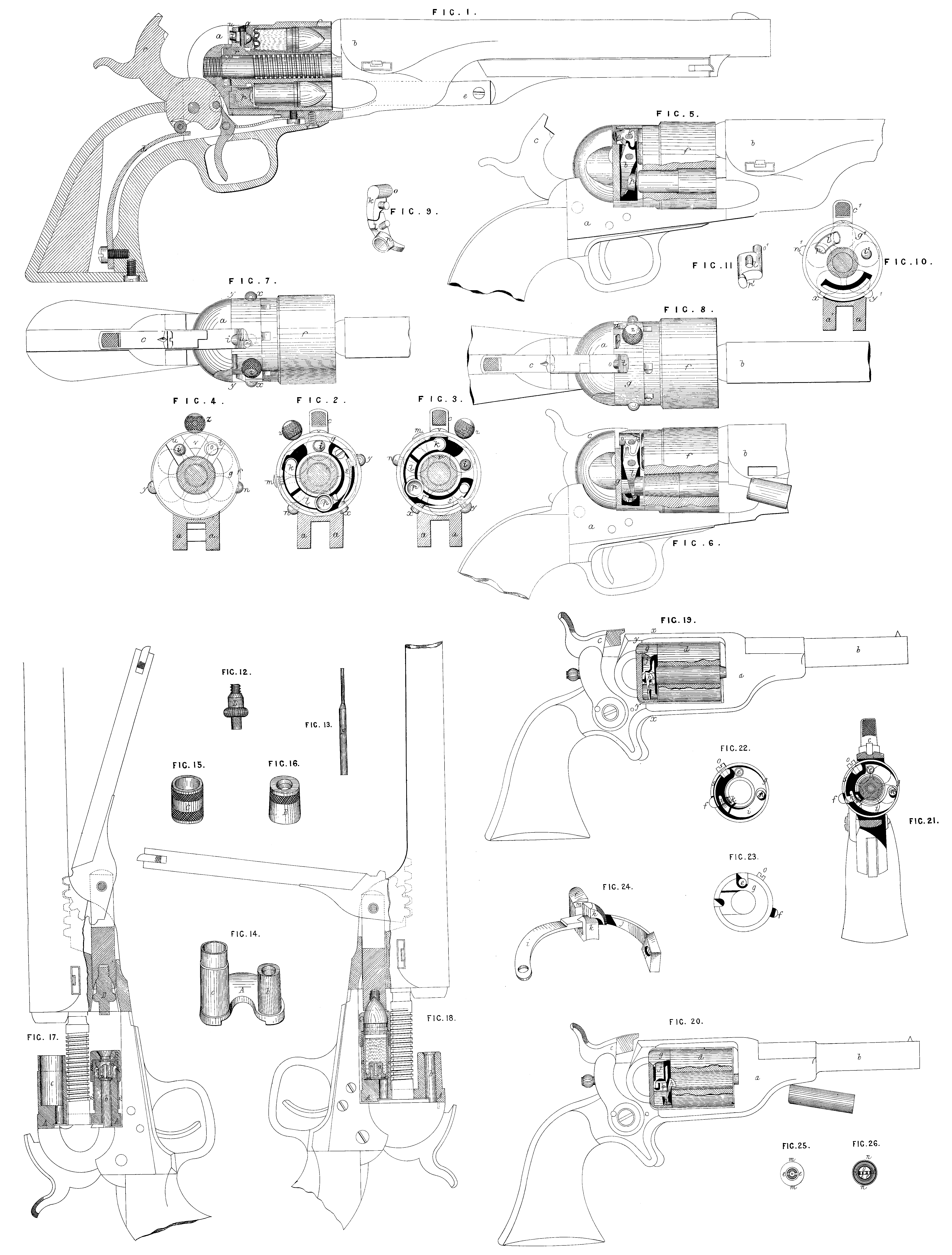
Figure 1 is a longitudinal section through the rear parts of an arm of the class known as Colt’s revolvers with my Invention applied thereto; Figure 2 is a transverse section on the line x, x, Figure 7, showing the ring g in the proper position to cause the ignition of a charge by the fall of the hammer; Figure 3 is a similar section showing the ring g in the proper position to cause the ejecting mechanism to be struck by the hammer; Figure 4 is a transverse section on the line y, y, Figure 7, looking forward, and showing the ring g turned into such a position that the hammer can strike neither the firing pin or the ejector; Figures 5 and 6 are side views of the arm with the ring g in the same position as in Figure 3, and with parts of the metal removed to show the contents of the ring and of one side chamber of the cylinder; Figure 5 shows the position of the parts when the hammer is at full-cock, and Figure 6 shows their position after the hammer has fallen and an empty cartridge case has been thereby ejected from the chamber; Figures 7 and 8 are plan views of the parts showing respectively the ring g in the positions of Figures 2 and 3; Figure 9 is a perspective view of the system of levers by which a blow of the hammer causes the ejection of a shell from a chamber not in line with the hammer. Similar letters of reference denote the same parts in the above-named Figures.
a represents the frame; b, the barrel; c, the hammer; d, the main spring; and e, the rammer of a so-called ” Colt’s ” pistol; these parts are in no manner changed from their usual forms and dimensions. The mechanism for rotating the cylinder ƒ also remains unchanged. f is the cylinder which may be made by turning off the rear part of the original cylinder far enough to expose the ends of all the chambers, the part in the rear of these being reduced to the diameter of the ratchet “, which remains unchanged. This leaves a space between the frame a and the ends of the chambers, the said space being nearly filled by a ring g which fits loosely around the rear part of the cylinder f. Its outside diameter equals that of the chambered part of the cylinder. The ring or annular plate g has in its face a deep annular groove, the ends of which nearly meet (see Figure 2). Through the solid metal between the ends of the groove a hole is drilled in which a firing pin or punch i is contained. This firing pin reaches through the ring from front to rear, and is of the proper length to transmit a blow of the hammer to the end of the cartridge which lies in line with the said hammer. The annular groove in the ring g contains a system of two curved levers k and 1, the fulcra of which are two screws m and n fixed in the ring. The first lever k has on its end a prong o which passes backward through a hole in the back of the ring g, its other end lies in front of one end of the second lever 1, the other end of which is provided with a large cylindrical protuberance or head p projecting forward to about the face of the ring g. A short extension of the lever beyond p is pressed upon by a spring s which forces back this end of the lever and thus causes the prong o on the end of the lever k to be protruded backward as far as possible. A recess t is cut in the back of the ring at the place where the prong o protrudes to give the face of the hammer access to the said prong. A similar notch u is cut in the back of the ring where the firing pin i passes through and another notch or recess v is made midway between t and u for a purpose herein-after explained. a is a spring, the free end of which projects beyond the periphery of the ring g; it serves by catching over one or the other edge of the frame a in connection with the heads of the screws y and n to hold the ring g in two different positions, respectively shewn by Figures 2 and 3. A ball z projecting from the ring serves as a thumb piece to move the ring about its axis into either of the positions above mentioned. The centres of the firing pin i, the prong o of the first lever k, and the head p of the second lever / lie in a circle corresponding with the centres of the chambers in the cylinder, and the length of the levers is such that when the ring stands in the position shown in Figure 3 the prong o is in line with the hammer and the head p of the lever corresponds with the second chamber to the right. When the ring stands as in Figure 2 the firing pin i lies in line with the hammer and will transmit its blow to the primer of the cartridge which is in line with the barrel.
The operation of this part of my Invention is as follows:— The chambers of the cylinder which may be taper are loaded from the front with metel cased cartridges in the same way as with the paper cartridges commonly used, the charges being rammed home with the rammer e. When it is desired to fire the charges the ring g is turned to the right by taking hold of the ball z, and the firing pin is thus brought in line with the hammer, as in Figures 1, 2, and 7; the charges may then be successively fired in the usual way by cocking and snapping the hammer. After firing the charges the empty metallic cases or shells may be ejected by turning the ring g to the left into the position shewn in Figures 3, 5, 6, and 8, and then operating the hammer by cocking and snapping it, as in the act of firing. The hammer now performs the additional function of ejecting the shells by striking the prong o of the lever k, which causes the head p of the second lever to start suddenly forward, and by thus giving a sharp blow to the end of each cartridge as they are successively brought into line with the head p the shells are forcibly ejected in a forward direction out of the chambers (see Figure 6). The chambers may be so tapered that the cartridges may be ejected without being fired. The head p is shewn with a recess in its face which permits it to strike only the edge of the cartridge. By this means when the cartridges are of the centre-fire variety I avoid the danger of causing their explosion by the ejecting blow. When it is desired to carry the arm loaded the ring g may be turned into the position shown by Figure 4; this brings the notch v into line with the hammer, which may be lowered so that its end enters the said notch and prevents the turning of the ring. The firing pin i is thus turned away from the front of the hammer and is left in a position where it is guarded by the frame from blows of any kind, while as there is no means of communicating a blow of the hammer to the cartridges their accidental discharge is fully provided against. I prefer to so proportion the chambers of the cylinder and cartridges that the rear ends of the said cartridges will protrude from the chambers far enough to permit the firing pin and ejector to perform their functions without entering the chambers. This prevents the liability of the rotation of the cylinder to be impeded if the pin or ejector should get out of order and tend to remain in their forward positions. The end of the firing pin is blunt and rounded so that it will be forced back by the ends of the cartridges when the cylinder is rotated; a thin extension of the periphery of the ring g hides the protruding ends of the shells.
Figure 10 represents a modification of the said Invention applicable particularly to the five-chambered cylinders, Figure 10 being a section corresponding with Figure 3, and showing the ring g in the ejecting position. Figure 11 is a perspective view of the ejector. l^1, s^1, is the firing pin arranged and operating in the ring g in the same manner as i in Figure 3. l^1 is the ejector, which consists of a short segmental piece sliding in a perforation through the ring g. This ejector is furnished with a prong o^1 its rear end for the hammer c¹ to strike against, and with a head p^1 at the forward end, which lies in line with the edge of the cartridge in the first chamber to the right of the hammer looking forward. The ejector l^1 is thrown bodily forward when struck by the hammer, and transfers the blow to the end of the shell which it ejects. The operation of this modification is the same as that of the one first described.
This Invention is also applicable to arms differing in construction from those commonly known as Colt’s fire-arms. In cases where the frame extends over the top of the cylinder, as in the weapon known as the “Remington” arm, the thumb piece on the movable plate g will need to be located on one side instead of on the top. New arms may be made embodying the said Invention, in which arms it may be well to attach to the frame, between the hammer and the cylinder, a movable piece which shall perform the functions of the ring g; as, for example, a segmental piece capable of a lateral movement around a hub concentric with the axis of the cylinder. This moveable piece may be hidden in the substance of that part of the frame called the recoil shield, and it may contain the firing pin alone, or the ejector, or both. Figures 12, 13, 14, 15, and 16 show the several parts of the attachment for loading the empty cartridge shells; and Figures 17 and 18 are side views of a pistol with the rotating breech removed, showing how they are applied and used. In these Figures similar letters denote the same parts.
A is a saddle piece fitting upon the recoil shield of the lock frame and around the pin on which the breech rotates. Attached to and forming part of this are the mandril b and cylinder c in such a position that when placed upon the arm they correspond with the position of the chambers in the breech, and either of them can be brought under the centre of the rammer by a movement around the breech pin. The mandril designed for holding the shell while the cap is placed upon it and forced home by the rammer, and the cylinder c is designed for holding the cartridge shell while being loaded with the powder, and the ball is forced down by the rammer. B is a short tube to be placed over the cartridge shell after it has been placed upon b to guide the cap in the operation of capping; C is a short tube to be placed on the end of the cylinder e to guide the ball into the cartridge; D is a piece to be screwed into the end of the rammer, as shewn in Figure 17, to press the cap into the recess of the cartridge; E is a pin for removing the exploded caps from the cartridge shells, and also when necessary to push the cartridges out from b and c from the under side of the saddle piece A.
The operation of this part of the said Invention is as follows:— When it is desired to reload the shells of expended cartridges the rotating breech is removed from the arm, and the piece A with the tubes b and c is placed upon the recoil shield. The piece D is screwed into the end of the rammer, and the shell, after having the old cap removed by the pin E, is placed upon the mandril b and brought under the rammer. The cap is then dropped into the hole in the top of the piece B and forced down by the rammer, the outside of the cap fitting into the recess formed in the cartridge case, as shewn in the Drawings by Figure 17. The piece b is removed and the shell taken off; should it stick to the mandril it can be loosened by pushing it from the bottom with the large end of the pin E. Having capped as many cartridges as are required the piece D is removed from the rammer, and the cylinder c is brought under it; the cartridge is inserted in c cap downward and the piece C placed over it. The shell is filled with powder and the ball properly lubricated placed upon it, and forced down to its place with the rammer, as shewn in Figure 18. The piece C and the cartridge are then removed. Should the cartridge stick in the cylinder it can be pushed out with the pin E. When a sufficient number of shells has been charged the rotating breech is replaced in the arm. Figures 17 and 18 show the construction of the cartridge used in this arm; Figure 25 is a view of the cap end and Figure 26 is a view of the open end of the empty cartridge shell. The outer tube m, n, is struck up or spun over a mandril in the usual manner, but near the bottom to the height of about one quarter of an inch at m the metal is left thicker than in the upper part of the shell at n. The block o of the exterior form shown in Figure 17 is then introduced into the outer shell, and firmly retained at the bottom of the tube by forcing down upon its lower flange, by means of a suitable punch the extra thickness of metal in the sides above it. This forms a rib or flange around the inside of the outer shell, as shewn in Figures 17 and 18. The cap tube is then cut out, as shewn in the above Figures, through the end of the outer shell and into the block o. Previous to its being placed in the shell the block o has a groove i, i, cut across its upper face, into which the circular groove for the cap penetrates, forming two apertures e, e, (see Figures 25 and 26). These serve to assist in communicating fire from the cap to the powder.
Figures 19 to 24 inclusive shew another form of ejector particularly suited to the smaller kinds of arms. Figure 19 is a side view of a so-called “Colt’s” pocket pistol with part of the side removed, shewing the ejecting mechanism in its ordinary position when the arm is in use; Figure 20 is a similar view with the ejector sprung in the act of throwing out the cartridge shell; Figure 21 is a section through the line x, x, of Figure 19, looking to the rear, and showing the parts of the ejecting mechanism in the same position as in Figure 19; Figure 22 is a similar section with the ejector sprung, as in Figure 20; Figure 23 is a section through y, y, Figure 19, looking forward; Figure 24 is an enlarged view of the working parts of the ejecting mechanism detached from the arm. The same letters in the above-mentioned Figures indicate the same parts.
a is the lock frame; b, the barrel; c, the hammer; d, the rotating chambered breech, which turns in the usual manner, but has its chambers open at the rear end, as before described; e is the firing pin; f, the thumb piece for operating the ejector; and g the ring containing the ejecting mechanism. This ring is stationary, and does not move laterally as heretofore described. h is the part of the ejector which operates upon the cartridge; it has a spring i to press it forward against the end of the shell, and is attached to the ring g by the screw n. The thumb piece f is furnished with a hook or detent k for holding back the ejector h, and is kept pressed outward by the spring j, which is secured to the ring g by the screw o. When the thumb piece ƒ is pressed inward the ejector h is released from the detent k and springs forward against the shell, as shewn in Figures 20 and 22. m is an inclined surface upon the thumb piece f for pushing out the shell a short distance, so that it will be free for the blow of h to eject it. This is so placed that it acts only when the thumb piece is pressed in, otherwise the end of the shell passes inside of it when the breech revolves.
The operation of this part of the said Invention is as follows:— After the arm has been discharged, and it is desired to expel the empty shells, the hammer is put at half- cock, and the thumb piece is pressed in, thereby springing the ejector h. Upon the breech being rotated by hand the edge of each shell as it comes opposite the thumb piece moves up the inclined surface m, and the ejector h passing over the end of the rotating breech suddenly springs into the chamber and ejects the shell. This continues until all the shells are thrown out, or until the thumb piece is released. When the thumb piece is allowed to spring out again to its normal position, and the arm is reloaded, the ends of the cartridges project out a little beyond the rear end of the breech, and push back the ejector h far enough to lock it under the hook k, where it remains secured until the thumb piece is pressed to release it.
This ejecting mechanism is suitable for an alteration of the arm above described from one using ordinary ammunition to one using metallic cased cartridges, but it may be applied to other arms, and may be placed, within the recoil shield instead of in a separate ring, as described.
Having thus fully described the said Invention, as communicated to me by my foreign correspondents, and shown how the same may be conveniently and advantageously carried into practice, I wish it under stood that I do not claim as new ejecting cartridge cases by blows of the hammer either direct or transmitted to chambers not in line with the hammer, nor the use of a ring or plate at the rear of the chambers containing the firing pin when the said plate is not movable in such a way that the firing pin may be moved out of range with the hammer; but I claim,—
First. The laterally moveable piece g containing the firing pin i in combination with the rotating chambered breech and the hammer of a revolver, substantially as described and for a safety device.
Second. A laterally moveable plate located between the hammer and cylinder of a revolver, and bearing the shell ejector, substantially as and for the purpose herein-before set forth.
Third. The combination of a movable piece supporting both the firing pin and an ejector with the hammer of a revolver and with a rotating breech having chambers open at the rear, when arranged to permit the use at will of the hammer either as a means of igniting the charges or of expelling the empty shells from the chambers, substantially as herein- before specified.
Fourth. The combination of the mandril 6, the cylinder c, and the saddle piece A (illustrated in Figure 14) when so constructed as to be applicable to a revolving arm for the purpose specified, substantially in the manner described.
Fifth. The reloading attachments, A, b, c, B, C, D, when used in combination with the lock frame and rammer of a revolving arm, substantially in the manner and for the purpose specified.
Sixth. The mode herein described of securing the cap block in the outer shell of the metallic cartridge case.
Seventh. The groove across the inner end of the cap block by which additional openings are provided to secure the ignition of the charge, substantially as herein described.
Eighth. The combination and arrangement shown in Figures 19 to 24 of the ring g, the thumb piece f, and the ejector h, with the rotating breech d, substantially as herein described.
Ninth. The thumb piece f, having an inclined surface m and detent k and the spring ejector h, when used in combination with a rotating chambered breech, substantially as described.
In witness whereof, I, the said Frederic August Kunow Waldemar von Oppen, have hereunto set my hand and seal, this Twenty ninth day of June, in the year of our Lord One thousand eight hundred and sixty-nine.
FREDERIC A. K. W. VON OPPEN. (L.S.)